- Login
- Sign Up
- Online referral form
This site is optimised for modern web browsers, and does not fully support your version of Internet Explorer, some sections of the website may not work correctly such as web forms


Shoulder arthrodesis
A patient-specific guide system has been used to facilitate bilateral shoulder arthrodesis in a Pekinese, and could be applied in other settings where alignment and reduction are anticipated particularly challenging, and / or when bone stock is limited.
Principles of osteotomy and reduction guide creation are similar to those described for limb deformity correction and fracture reduction. CT data is processed to obtain a 3D representations of the shoulder (Figure 1). This is imported into CAD software, and virtual 3D models of the humerus and scapula created. Virtual reduction of the shoulder is performed ensuring optimal alignment in all planes; virtual osteotomies of the glenoid and humeral head are then made (Figure 2). For each bone a virtual osteotomy guide is created; key features include a contact surface comprising an inverted virtual representation of a segment of cortex (such that the finished guide fits onto the cortex in a unique position), an osteotomy plane to guide the oscillating saw blade, and two Ellis pin channels (Figure 3). Subsequently a virtual reduction guide is created; when applied over the Ellis pins, the planned orientation of the ostectomised scapular and humerus results (Figure 4). These guides, as well as the original humerus and scapula, and the reduced humeroscapular unit, are 3D printed (Figure 5). Plates can be pre-contoured to the latter model (Figure 6), and can be applied with minimal further contouring time after guided osteotomy and reduction in theatre (Figure 7). Post-operative and follow-up radiographs from this case are shown in Figure 8.
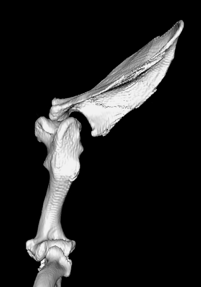
Figure 1 – Surface rendered image of the left shoulder showing severe medial instability and a minimally displaced fracture of the spinous process
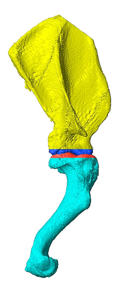
Figure 2 – Images from CAD software. Virtual reduction of the 3D mesh representations of the right humerus and scapula. The positions of parallel, virtual glenoid and humeral head osteotomies are represented by the colour changes; all four bone segments can be manipulated in all planes independently. Note the marked sagittal-plane sigmoidal conformation resulting in atypical osteotomy orientation.
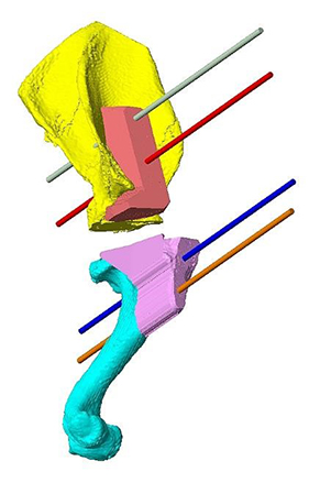
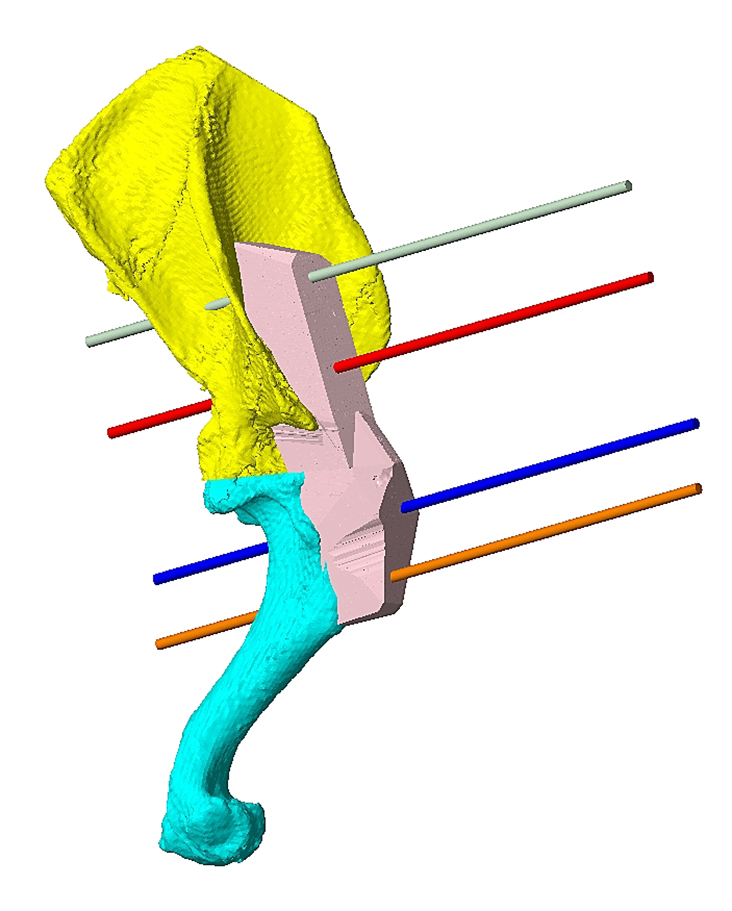
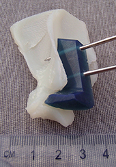
Figure 3 - The completed virtual glenoid and humeral head osteotomies. Virtual osteotomy guides have been created with contact surfaces conforming to the underlying cortical contour, two channels for 1.6mm Ellis pins, and flat surfaces in the same plane as the virtual osteotomy planes.
Figure 4 - Reduction of the ostectomised humerus and scapula with the virtual reduction guide in situ.
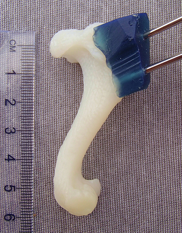
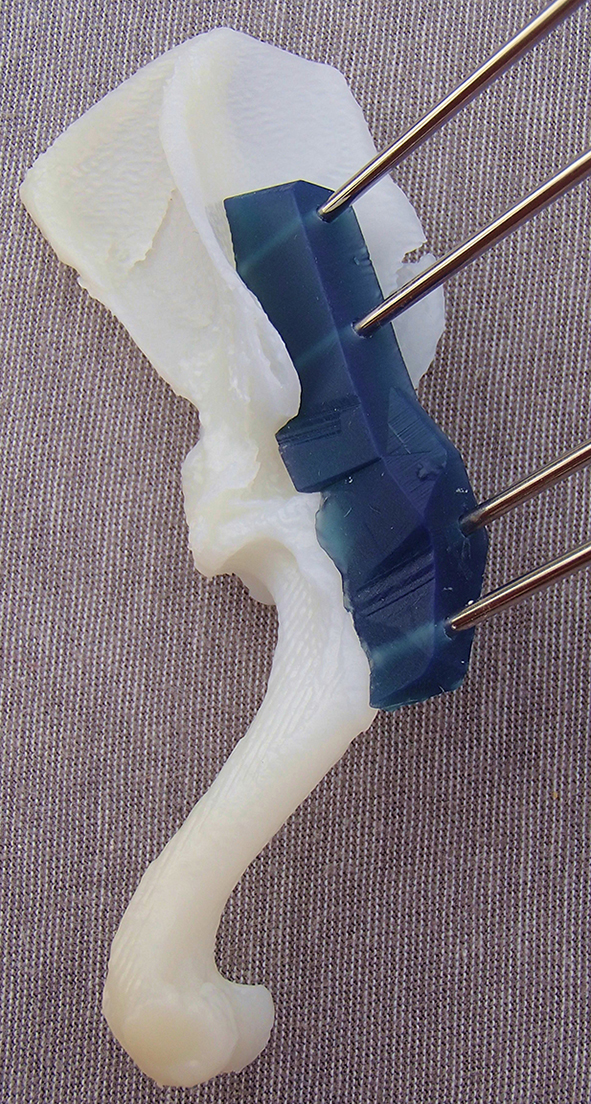
Figure 5 – Re-printed models of the scapula, humerus and reduced humerus-scapula unit, with their respective guides attached with Ellis pins.
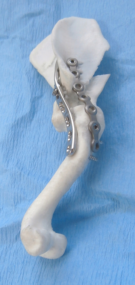
Figure 6 – Plates can be precontoured, and in this case were applied to the humerus-scapula model to ensure maximisation of screw bone stock in the scapula (the tips of the two proximal caudolateral plate screws are visible through the paper thin scapular body.
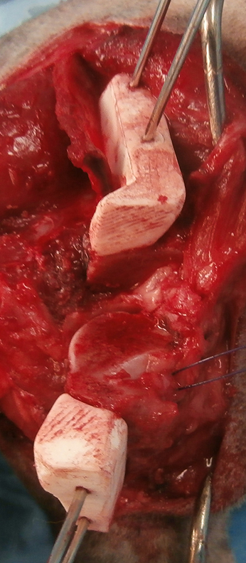
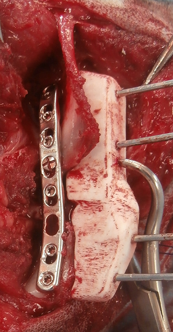
Figure 7 - Intra-operative image showing the humeral and scapular osteotomy guides in-situ attached with 1.6mm Ellis pins; both osteotomies have been made in the same plane as the appropriate surface of each guide (A). The reduction guide slides down all four Ellis pins reducing the osteotomy (B). The pre-contoured 2mm LCP has been applied caudolaterally; the reduction guide and Ellis were then removed, and a second plate applied craniolaterally.
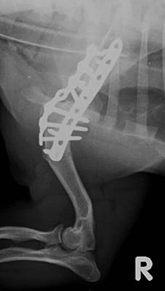
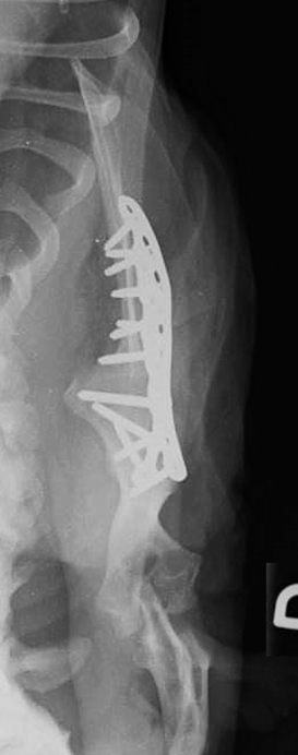
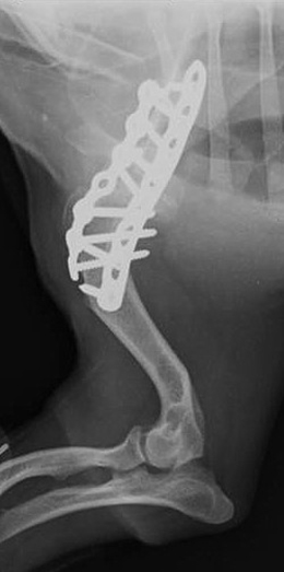
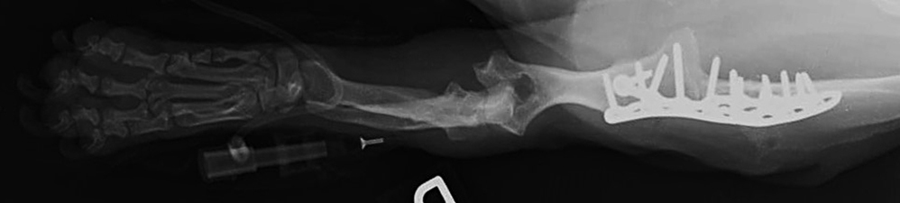
Figure 8 – Radiographs of the right shoulder. Post-operative mediolateral (A) and craniocaudal (B). Eight week follow-up mediolateral (C) and craniocaudal (D).
©Copyright 2017 - Vet 3D | Terms & Conditions | Cookie Policy