- Login
- Sign Up
- Online referral form
This site is optimised for modern web browsers, and does not fully support your version of Internet Explorer, some sections of the website may not work correctly such as web forms


Humeral Intracondylar Fissure (HIF/IOHC) – Transcondylar Screw
Humeral intracondylar Fissure (HIF), also described as Incomplete Ossification ofthe Humeral Cpndyle (IOHC) is probably the most common cause of forelimb lameness in yound to middle-aged Springer Spaniels, and less frequently affects other breeds also. When left untreated fissures can progress to uni- or bi-condylar fractures.
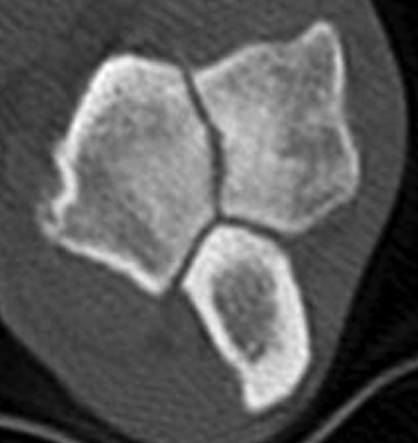
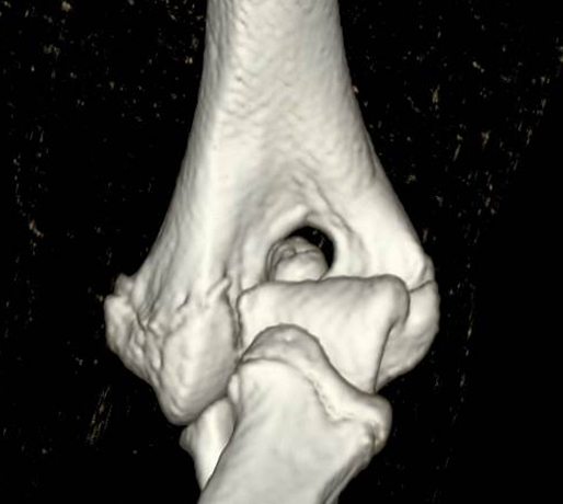
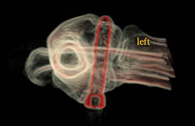
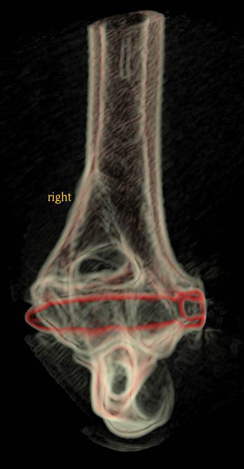
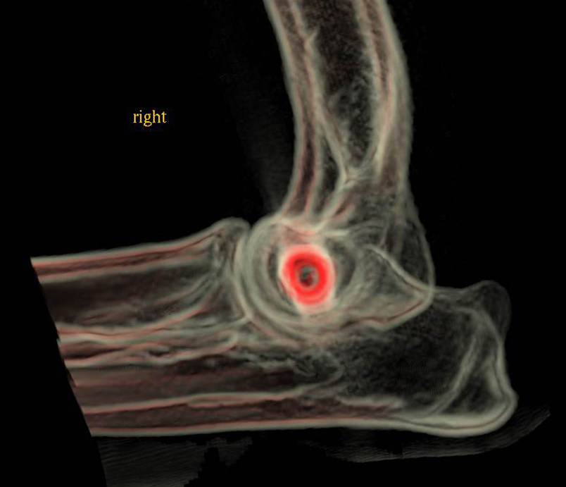
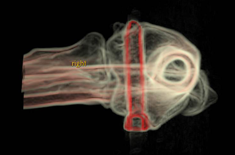
Transverse and volume-rendered CT images showing a complete humeral condylar fissure
The aetiopathogenesis of humeral intracondylar fissure (HIF) is not known. When first described by Denis Marcellin-Little in 1994, persistence of the anlage cartilage at the mid-point of the humeral condyle was suspected and the term Incomplete Ossification of the Humeral Condyle (IOHC) adopted. However, subsequent evidence has shown the condylar fissure to be acquired, with histopathological features consistent with a stress fracture. It follows that a shear force acting between the medial and lateral portions of the condyle may be present (Figure 1). Persistence of this force may result in eventual cyclic failure of inadequately sized transcondylar implants (Figure 2). A large implant capable of resisting long term cyclic loading is therefore rational, but necessitates accurate placement across the condyle. Several strategies are available including drilling based on palpable landmarks, the use of aiming devices, and fluoroscopy.
Intellectual Property Office Registered Design number 6003204
3D printing
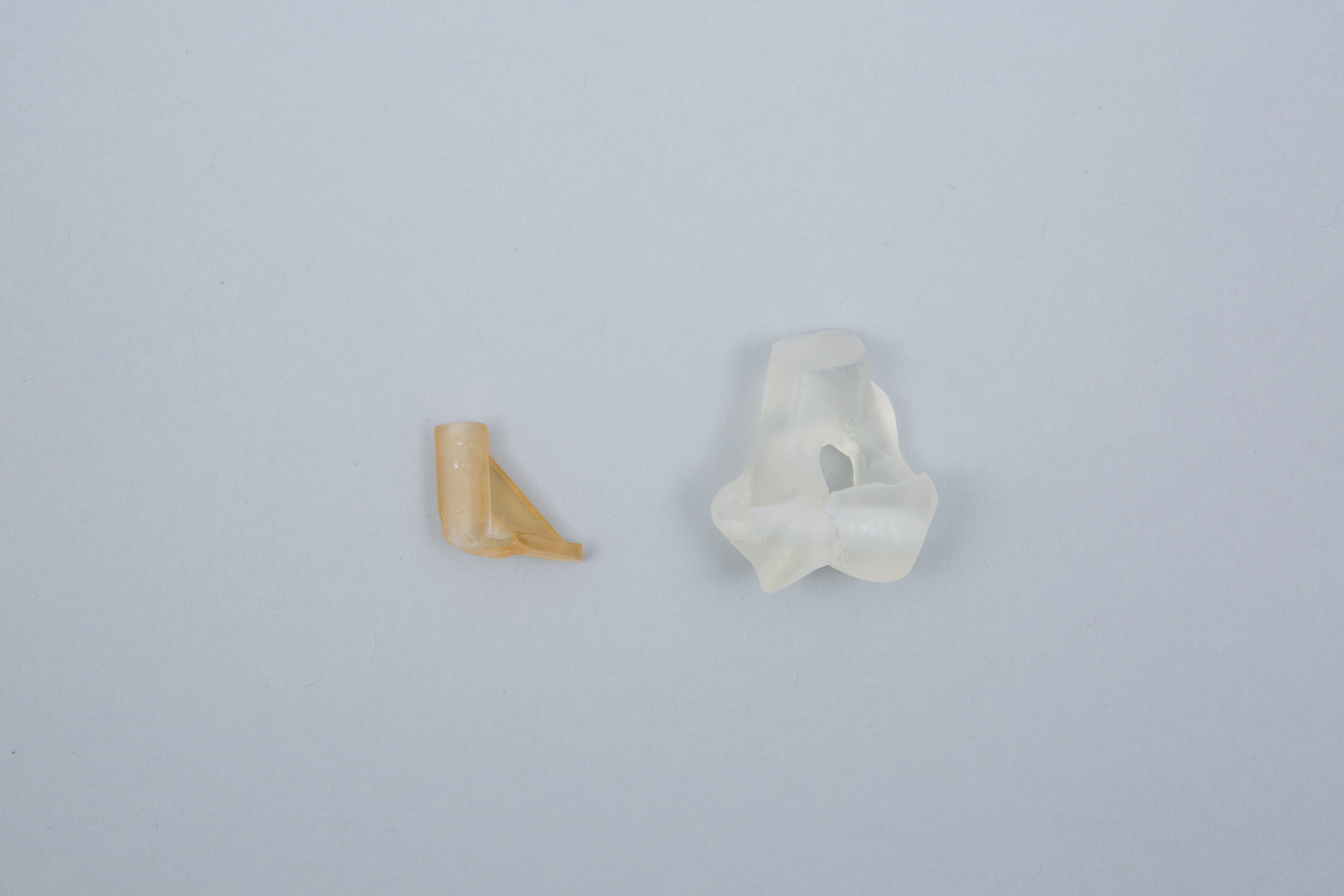
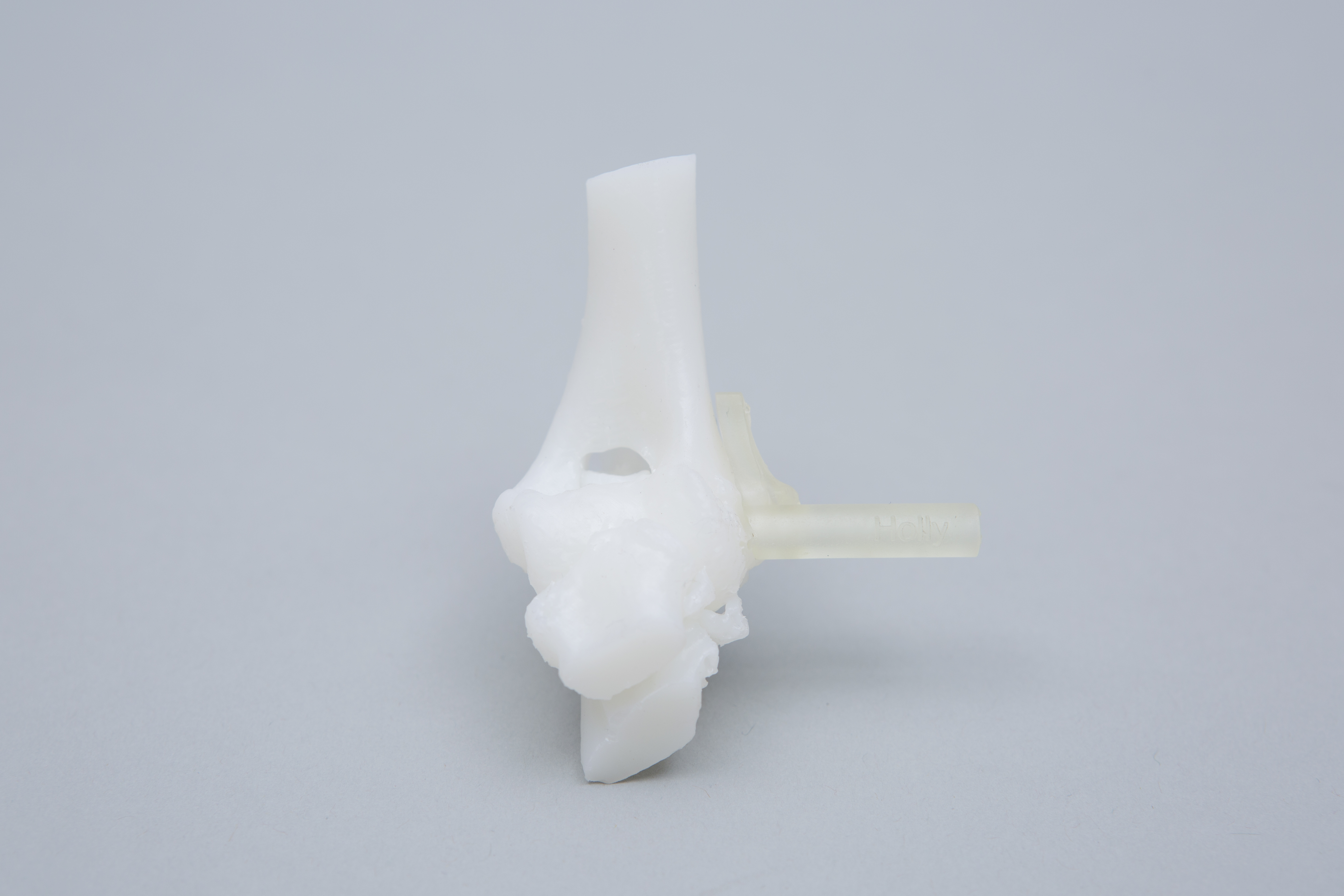
For most cases the following models and guides are printed (Figure 13) –
- Humeral condyle with pilot hole of specified size (usually in autoclavable plastic)
- Drill guide (single or sequential as specified) in autoclavable and biocompatible plastic
Please see Price Guide for additional information
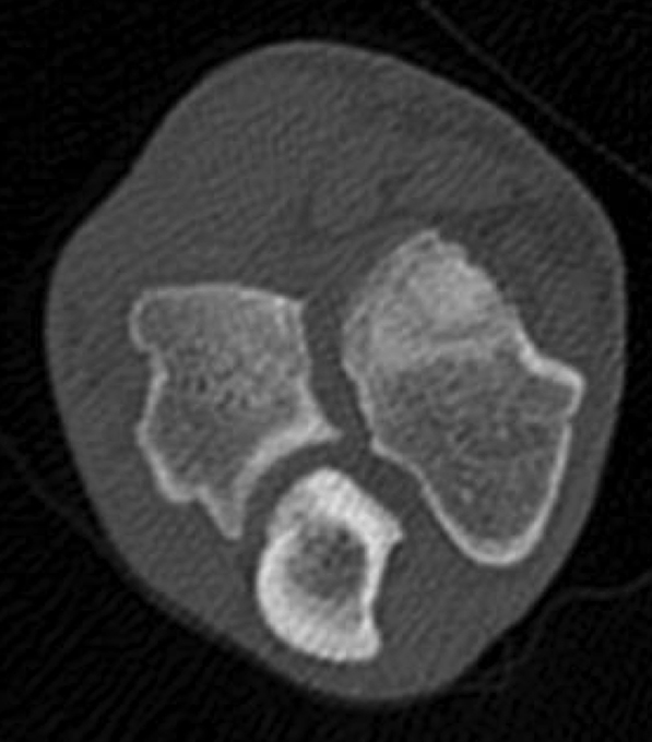
Figure 12 – A humeral fissure in a 5 month old pug; note the width of the fissure and the absence of adjacent sclerosis.
IOHC
It is probable that a second form of humeral condyle fissures occur in young, small breed dogs. Again the aetiopathogenesis is unknown but may more akin to true IOHC than HIF lesions in skeletally mature dogs. Fissures in these cases are often very large, lack adjacent sclerotic margins, and frequently occur in association with condylar dysplasia (Figure 12). Transcondylar implant placement is complicated by the small size of these patients, the frequently relatively oblique orientation of the condyle, and atypical anatomic landmarks. Patient-specific drill guides can be created in most cases.
Figure 11 - Post-operative CT images following guided placement of bilateral transcondylar 5mm titanium locking screws in a 19kg female springer spaniel.
Guide placement is via a direct approach over the medial epicondyle. The origin of the flexor carpi radialis (FCR) muscle is elevated from the distal aspect of the medial epicondyle, and any soft tissue adherent to the cortex in the area of the guide footprint removed to optimise guide fit. Once the guide is positioned the pilot hole is drilled and the implant placed. The FCR is sutured to a loop tied around the screw head, or to a 1.5mm tunnel drilled in the medial epicondyle. Fascial layers are closed carefully to minimise the risk of seroma formation. Once familiar with guide application, surgical time is approximately 20 minutes. Figure 11 shows post-operative CT images following guided placement of bilateral transcondylar 5mm titanium locking screws for treatment of humeral intracondylar fissures in a 19kg female springer spaniel.
Figure 8 – The diameter of the cylinder had been reduced to that of the desired pilot hole (2.5mm), and drill sleeve created (A). The contour of the bone contact surface of the guide precisely reflects that of the patient’s medial epicondyle and an adjacent region of cortex (B).
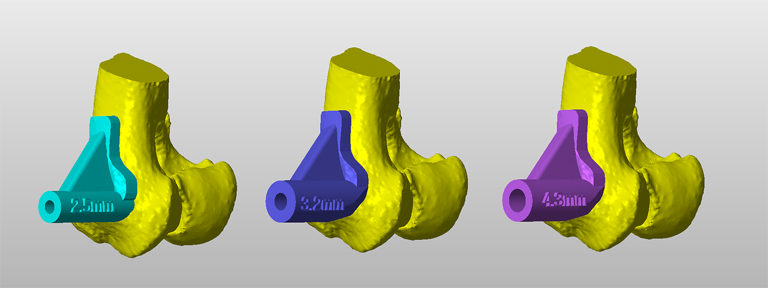
Figure 9 – Three drill guides for sequential pilot holes drilling.
Figure 10 – The 3D-printed condyle with a drill guide in-situ on the medial aspect of the condyle. The guide is printed in biocompatible, autoclavable plastic.
Once finalised, the diameter of the trajectory is reduced to the desired pilot hole size, and a drill sleeve created around the trajectory. The second key element of the drill guide is a bone contact surface that precisely reflects the contours of the patient’s medial epicondyle and an adjacent area of cortex. In this way, the finished guide will fit only in a single, unique position, thus appropriately orientating the drill sleeve relative to the condyle (Figure 8). Guide fit is usually excellent due to the highly contoured nature of the medial epicondyle.
When a large pilot hole diameter is required (for example 4.3mm for a 5mm locking screw), sequential drilling starting with a much smaller bit is usually preferred. In this example three guides for pilot hole diameters of 2.5mm, 3.2mm and 4.3mm could be designed (Figure 9). Alternatively, some surgeons prefer a single 2.5mm guide, with non-guided over-drilling to the appropriate diameter. Drill guides are 3D printed in biocompatible, autoclavable plastic (Figure 10).
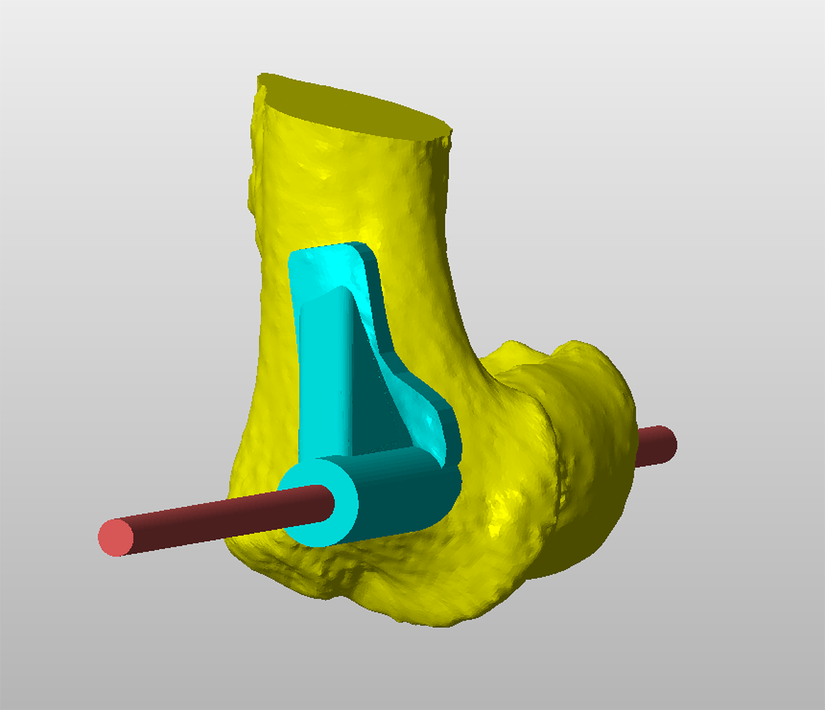
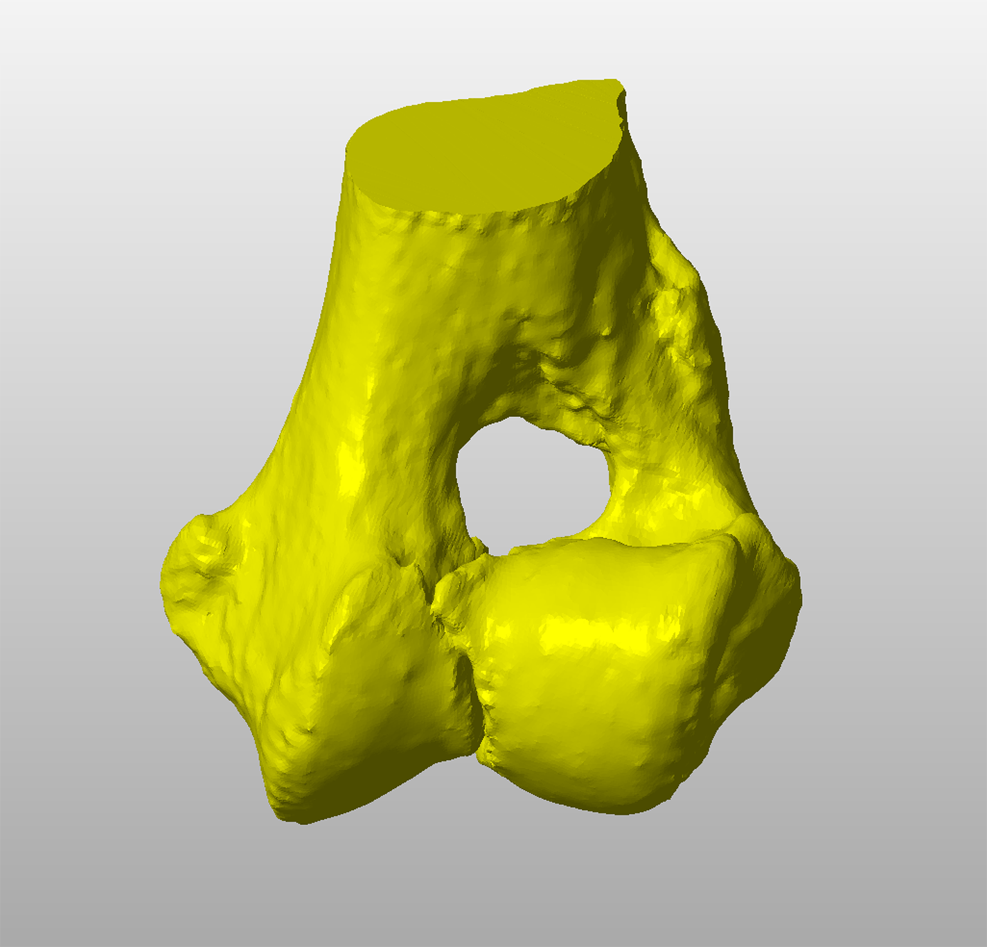
Figure 3 – A virtual 3D representation of a fissured humeral condyle in CAD software.
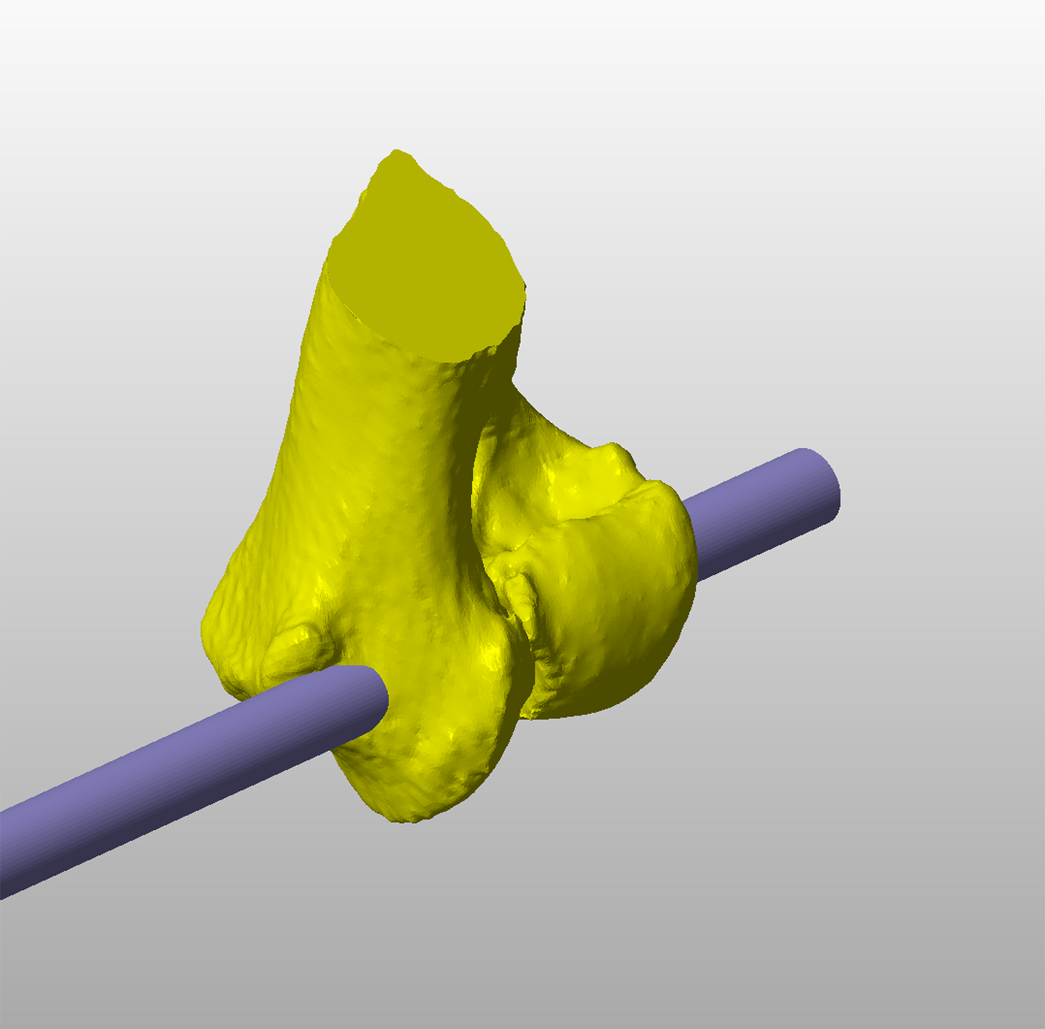
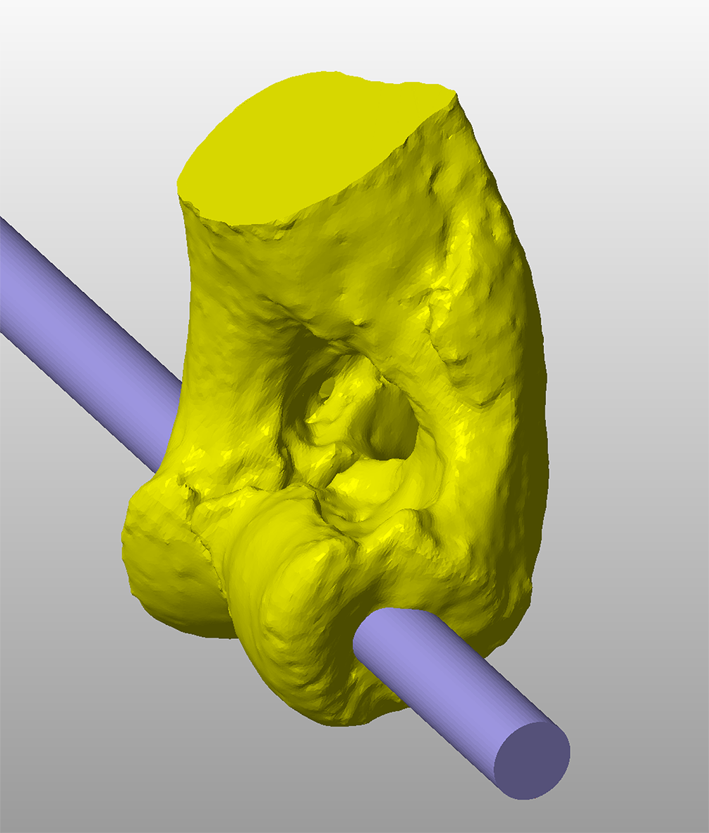
Figure 4 – A cylinder representing the virtual trajectory of a transcondylar implant is created. In this example a 5mm locking screw is planned, therefore the cylinder diameter is also 5mm.
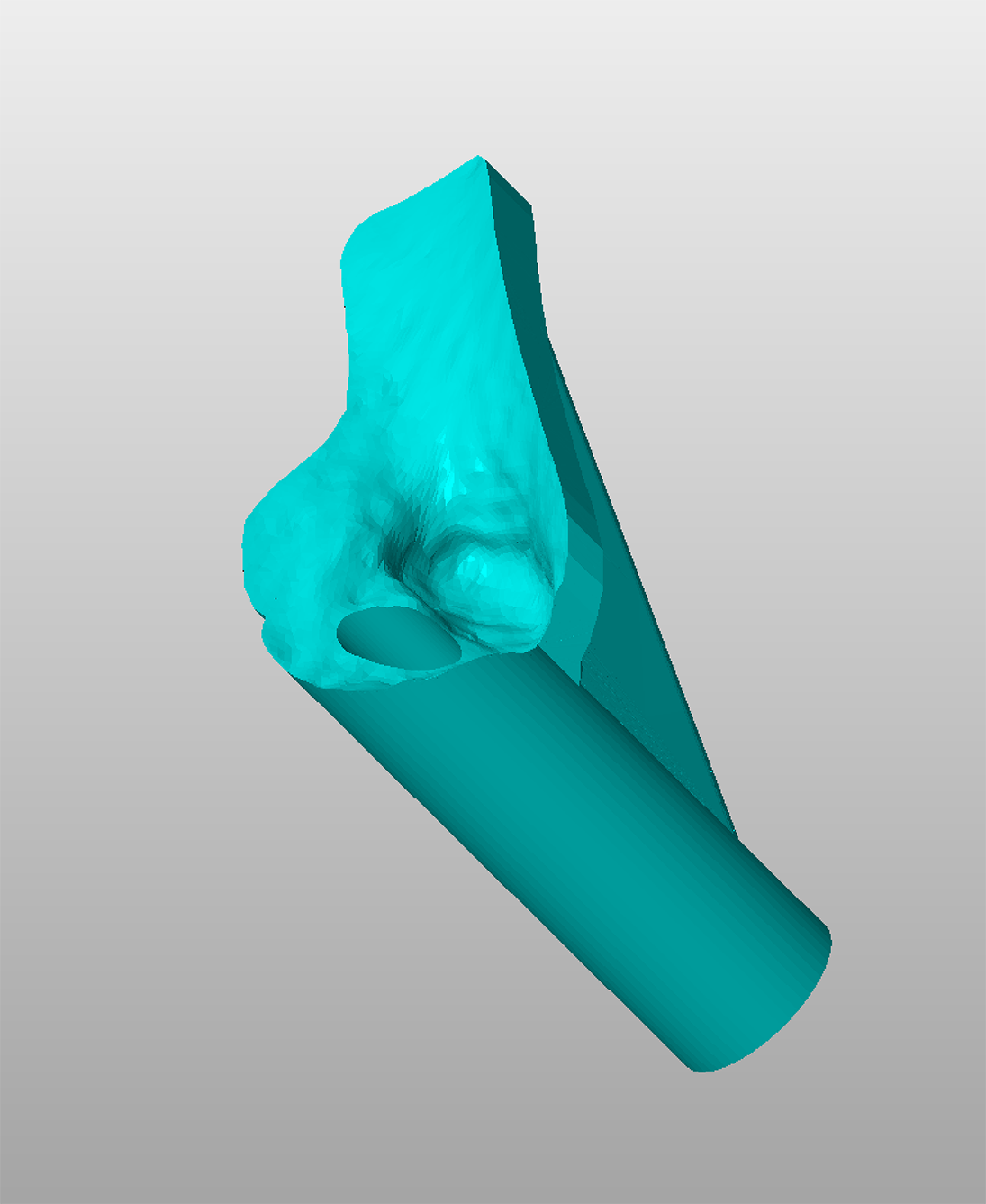
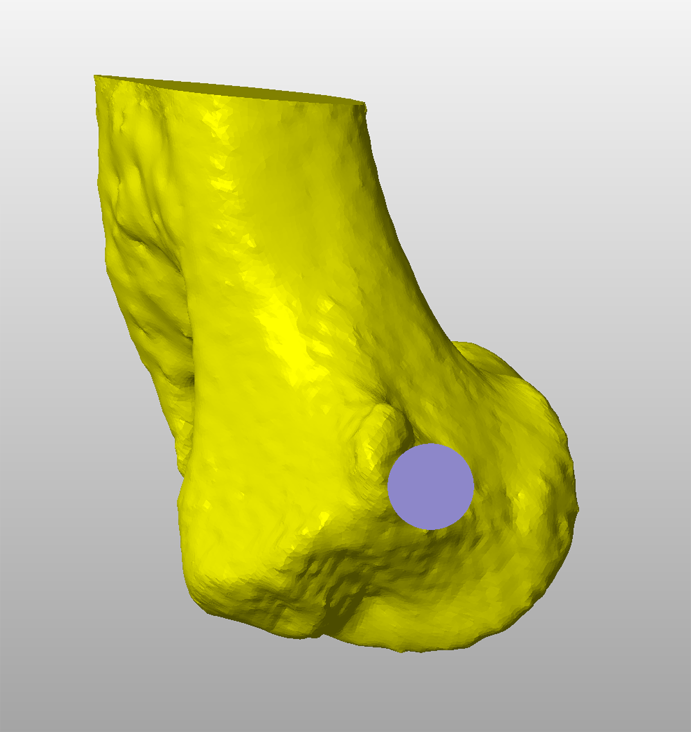
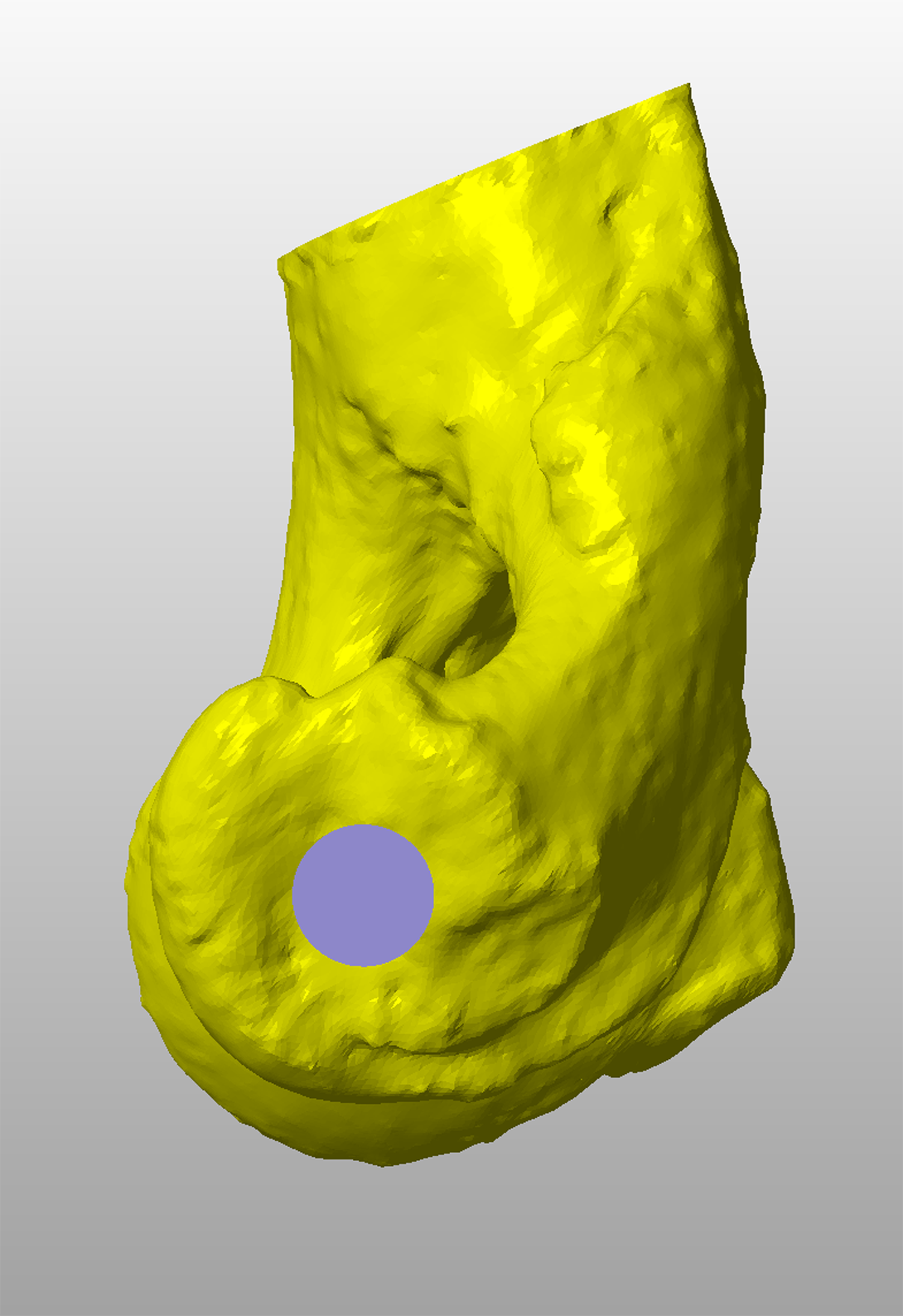
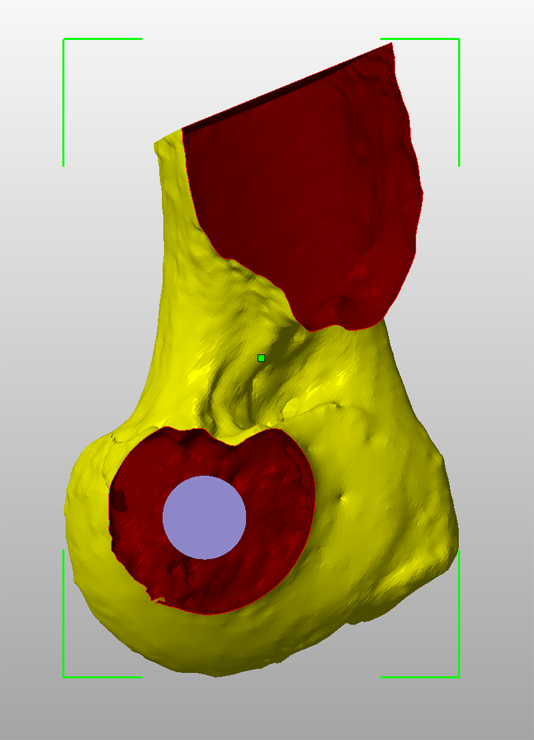
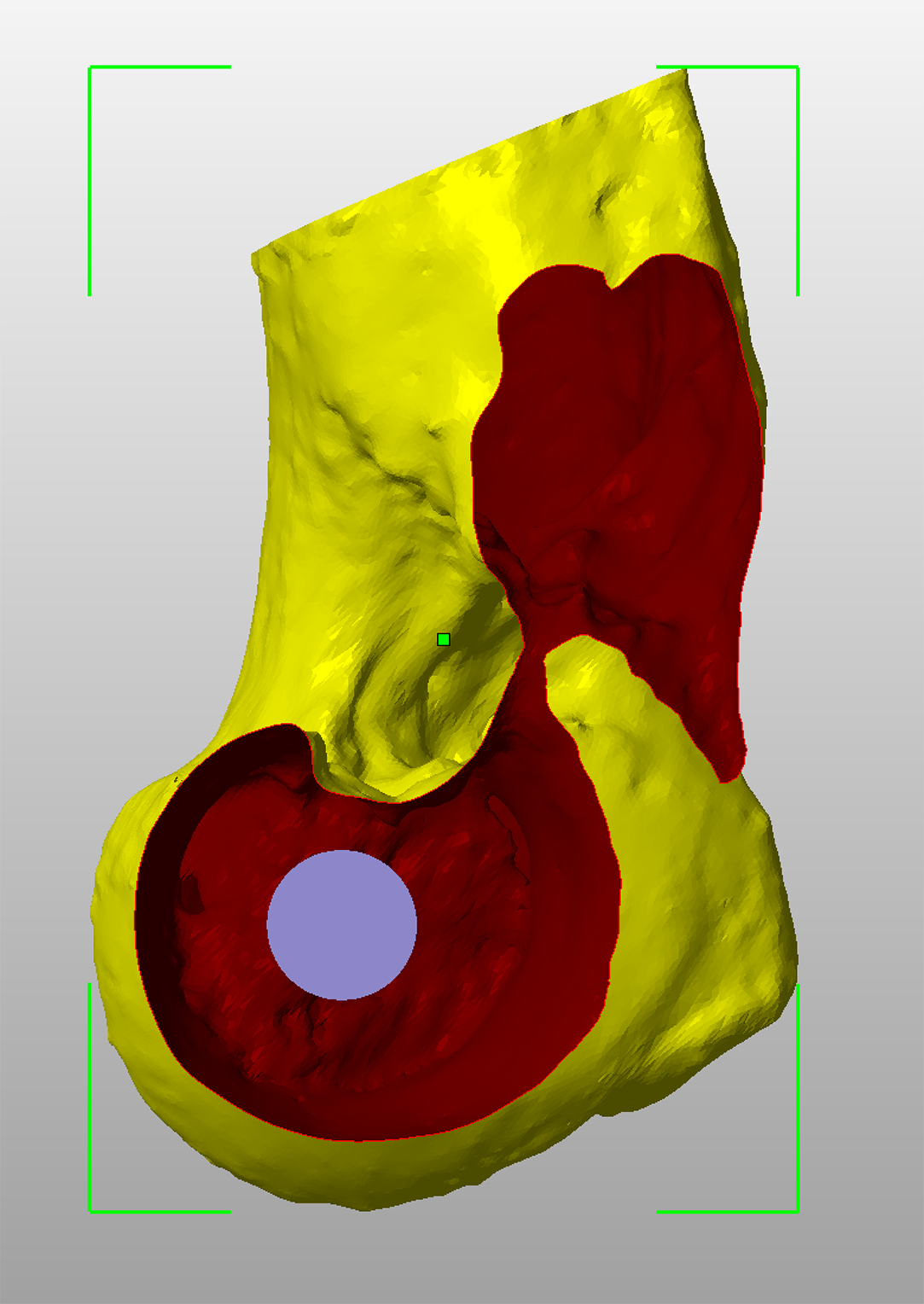
Figure 5 – A medial view of the condyle showing the entry point of the virtual screw trajectory immediately distal and cranial to the medial epicondyle (A). A lateral view showing the exit point centrally within the slight concavity distal to the lateral epicondyle.
Figure 6 – A sagittal cross-sectional view at the condylar isthmus. The virtual screw trajectory is adjusted to be central at this point.
Figure 7 – There is frequently a quite marked depression in the dorsal aspect of the condyle laterally (A); a screw placed parallel to the dorsal plane will be very close to, or breach, the cortex at this point. The virtual screw trajectory is adjusted slightly distally to avoid the dip in the dorsal cortex (B).
Patient-specific drilling guides for transcondylar implant placement are designed based on CT data. This is used to create a virtual 3D representation of the condyle in CAD software which can be viewed from any angle or in cross-section (Figure 3). A cylinder with the same diameter as the planned transcondylar implant is created, representing its virtual trajectory across the condyle (Figure 4). This trajectory can be adjusted in six degrees of freedom until optimised. Key criteria include –
· Appropriate entry and exit points adjacent to the medial and lateral epicondyles respectively (Figure 5).
· A central position at the isthmus of the condyle (Figure 6).
· A safe margin to the dorsal aspect of the condyle laterally, where a depression is often present (Figure 7).
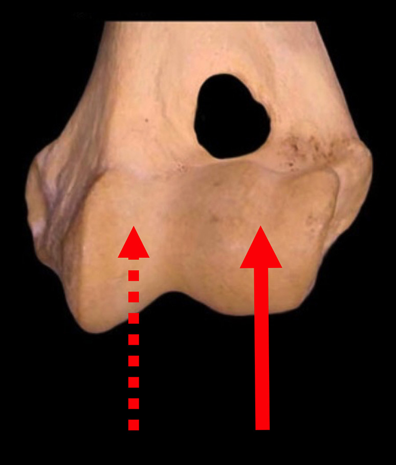
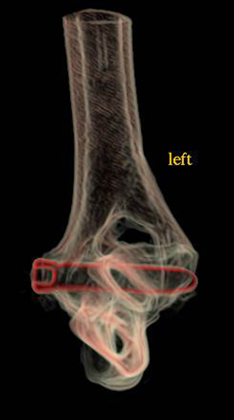
Figure 1 – In dogs with humeral condylar fissures a shear force may exist between the medial and lateral aspects of the condyle.
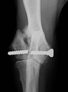
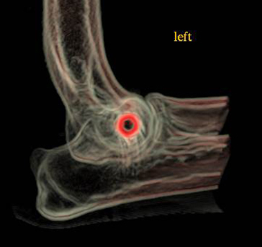
Figure 2 – A transcondylar cortical screw placed to treat a humeral condylar fissure has failed with concurrent fracture of the lateral portion of the condyle.
©Copyright 2017 - Vet 3D | Terms & Conditions | Cookie Policy