- Login
- Sign Up
- Online referral form
This site is optimised for modern web browsers, and does not fully support your version of Internet Explorer, some sections of the website may not work correctly such as web forms


Medial Patellar Luxation – Femoral Osteotomy
The role of abnormal femoral conformation in the aetiopathogenesis of patellar instability has become increasing recognised over the last 10 years. Both increased femoral varus, and external torsion, will medialise the line of action of the quadriceps, and thus the patella, with respect to the trochlea. Conversely, femoral valgus, and / or internal torsion may result in lateral patellar instability. In such cases several studies have demonstrated excellent clinical outcomes following femoral osteotomy.1,2
Optimisation of femoral deformity correction in this context requires three key steps –
· Precise quantification of femoral conformation.
· Knowledge of “normal” values (i.e. the target for correction).
· The ability to accurately achieve the planned angular correction(s) in theatre with the least possible tissue handling and surgical time.
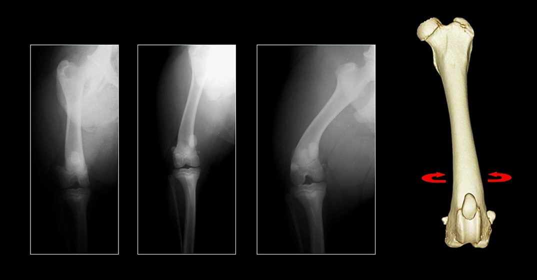
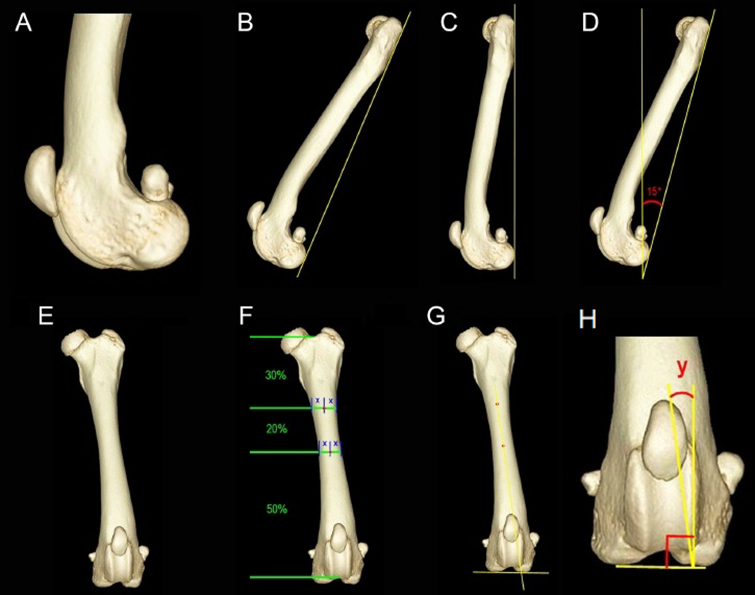
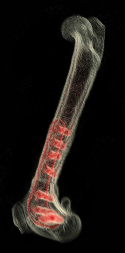
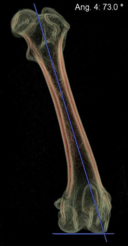
Traditional radiographic measurement of femoral varus is sensitive to rotational malpositioning of the femur because of the natural procurvatum of the bone; external rotation (supination) will increase apparent varus, and vice versa (Figure 1). Thus a “true” craniocaudal radiograph must be obtained. Unfortunately the majority of radiographic landmarks to achieve this positioning (including fabellar bisection by the femoral cortices, lesser trochanter position, and nutrient artery foramen position) have been shown to be unreliable. CT permits visualisation of a virtual representation of a femur from any angle, rendering patient positioning irrelevant and facilitating deï¬nition of landmarks for rotational and sagittal plane orientation which would be impossible using conventional radiography. Using a volume rendered representation of the femur, superimposition of the medial and lateral condyles, and standardisation of sagittal plane inclination (Figure 2), allows precise quantification of femoral varus.3 Traditional radiographic assessment of femoral torsion is difficult since a long axis projection is usually required. This is straightforward following CT, and a protocol for precise torsion measurement has been described.4
Figure 1 – Craniocaudal projections of the same femur at different amounts of rotation; apparent varus is decreased with internal rotation and increased with external rotation.
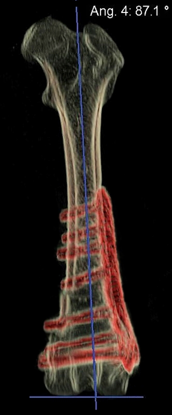
Figure 2 – Protocol for standardized femoral orientation. Perfect superimposition of the most caudal and most distal points of the femoral condyles is achieved (A). An axis is drawn between the most caudal points of the femoral condyles and the proximal femur (B). The image is rotated in the sagittal plane until this axis is vertically orientated (C), and then rotated further such that the axis is caudally inclined by 15° (D). The image is then rotated through 90° in the transverse plane to yield a cranial view of the femur (E). The centre of the diaphysis is identiï¬ed at 50% and 70% of the distance between the most distal apparent extent of the intertrochanteric fossa and the most proximal apparent extent of the intercondylar notch (F). These points are connected to deï¬ne the proximal anatomic femoral diaphyseal axis (PAA); the transcondylar axis (TCA) is deï¬ned as a line connecting the most distal points of the femoral condyles (G). Femoral varus angle (angle y) is the angle between the PAA and a line perpendicular to the TCA (H).
Although breed-specific “normal” values have not been established using CT, it must be remembered that the majority of published values are based on measurements made using conventional radiographic landmarks and may therefore be subject to errors introduced by malpositioning. It is probably unwise to define specific thresholds for varus and torsion above which femoral osteotomy should be performed. When femoral varus angle is <8° (i.e. aLDFA <98°) femoral osteotomy is probably not indicated, between 8-12° (aLDFA 98-102°) is borderline, and when >12° (aLDFA >102°) osteotomy may well be appropriate. Abnormal torsion is even harder to define; detorsional osteotomy is probably most appropriate when version angle approaches zero.
The third challenge is to accurately achieve the planned angular correction in theatre. Optimal execution of the planned osteotomy requires several key steps –
1. Accurate identification of the position of the CORA on the femur
2. Appropriate positioning of the osteotomies relative to the CORA
3. Planned saw blade orientation must be maintained for both osteotomies
4. Reduction about the planned angulation correction axis
5. Maintenance of accurate reduction whilst fixation is applied
The use of a TPLO jig or a Deformity Reduction Device can facilitate steps 4 and 5 (although both have potential drawbacks5), however steps 1-3 can be challenging, especially in small patients.
Virtual surgical planning
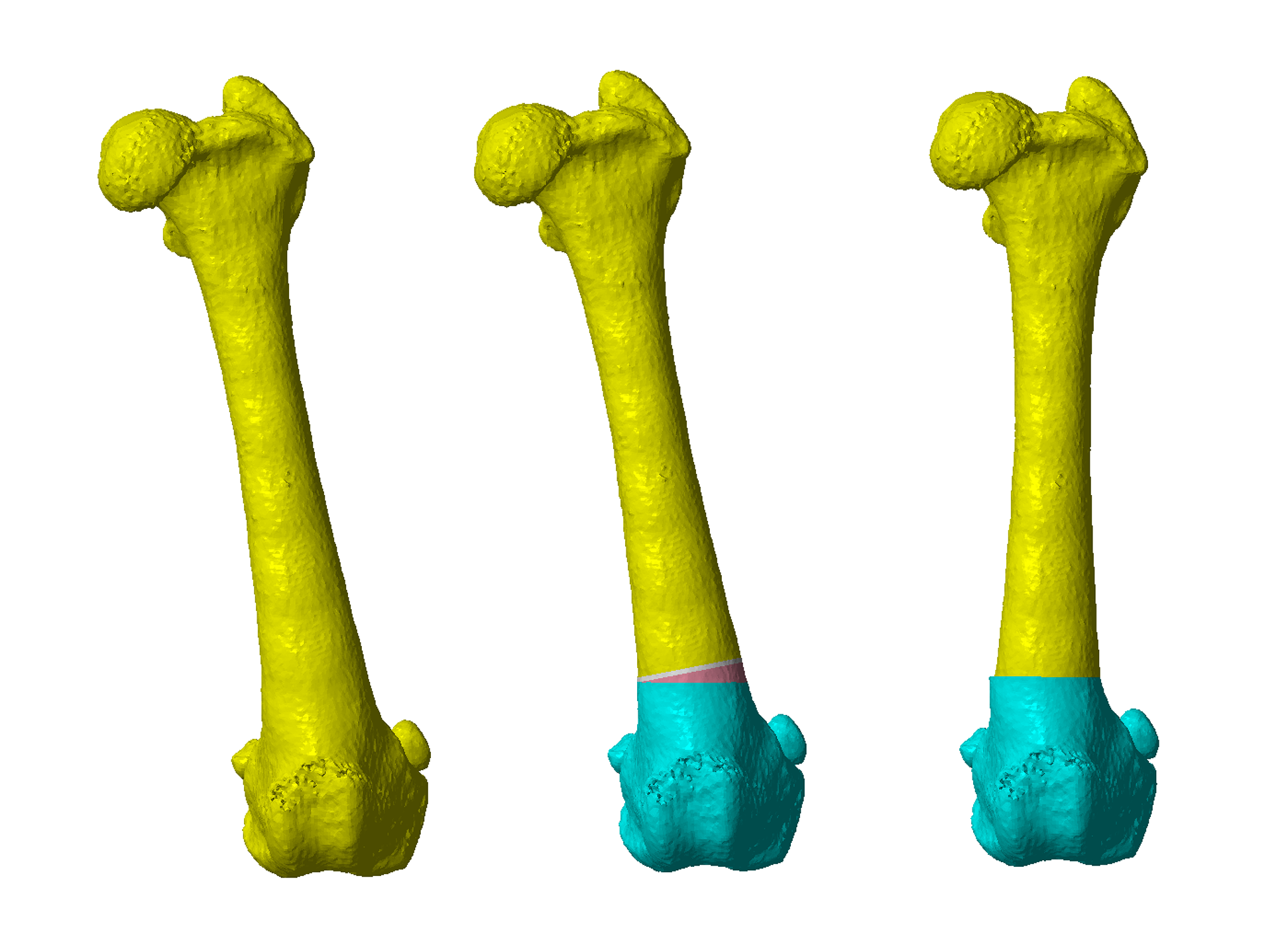
Femoral varus and torsion can be quantified at various points – on the CT workstation, using medical image processing software, or following export of the CT data to CAD software. Once a virtual 3D model of the femur has been created in the CAD software, this can be reoriented in any plane, the appropriate CORA identified, and correction planned. Virtual osteotomies are then made based on CORA position and the degree of frontal plane and/or torsional correction required (Figure 3).
Figure 3 – A virtual 3D model of the left femur with a femoral varus angle of 17° (aLDFA 107°). A virtual 14° laterally based closing wedge ostectomy has been performed at the CORA, and the major osteotomy segments reduced.
Osteotomy and reduction guide design
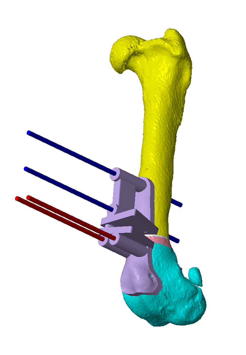
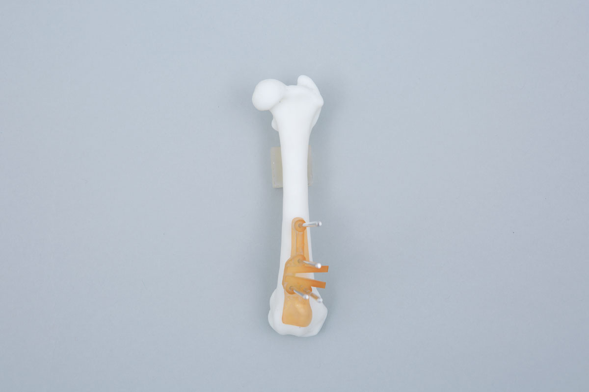
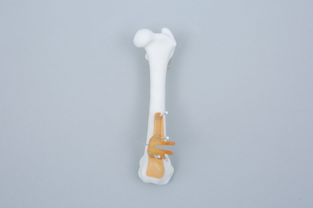
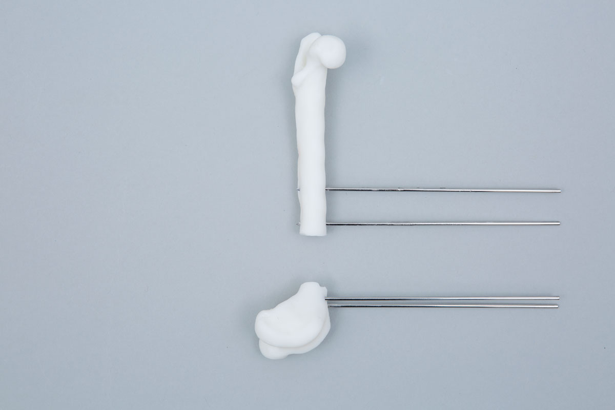
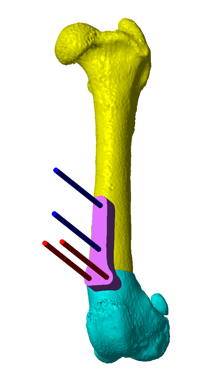
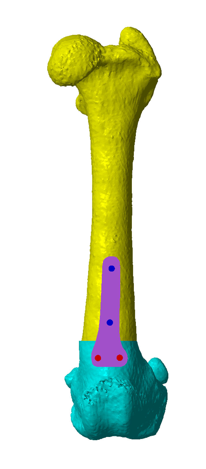
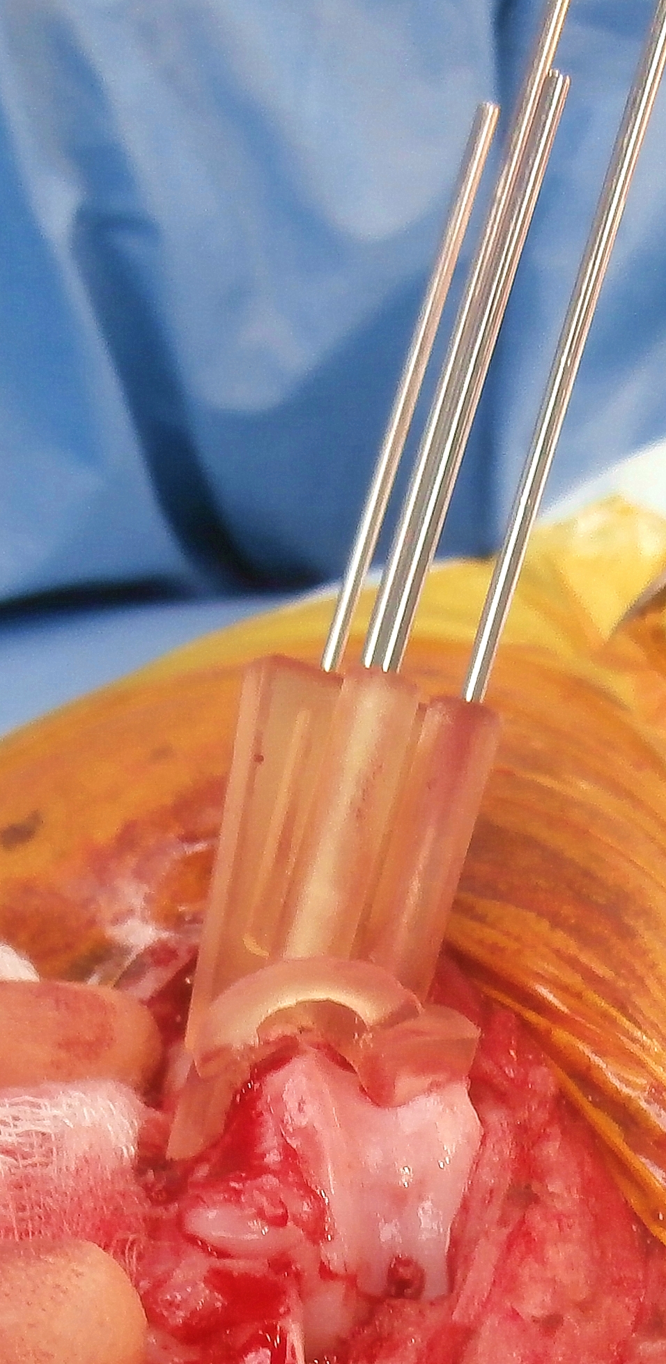
Once osteotomy position and distal segment reorientation are determined, osteotomy and reduction guides can be created. The key feature of the osteotomy guide is a contact surface which precisely reflects that of the femoral cortex to which it will be applied. The guide therefore fits only in a specific, unique location, thereby precisely defining the relative positions and orientations of osteotomy plane guide surfaces and channels for placement of Ellis pins which secure the guide to the bone (Figure 4). The highly contoured surface provided by the proximal trochlear ridges usually gives excellent guide fit. The osteotomies are made with an oscillating saw aligned to the guide planes (Figure 5). The guide is then removed, but the Ellis pins left in-situ (Figure 6). The original trajectories of the pins are designed such that when these are aligned in parallel by the reduction guide the femur is reduced to the pre-planned orientation (Figure 7). The guide maintains reduction whilst a plate is applied (this plate can be precontoured to a 3D printed model of the post-reduction femur) (Figure 8). Figure 9 shows post-operative CT; varus correction closely approximate to that planned. Intra-operative images from another case are shown in Figure 10.
Concurrent varus and torsional corrections, and torsional corrections only, can be planned and performed in the same way.
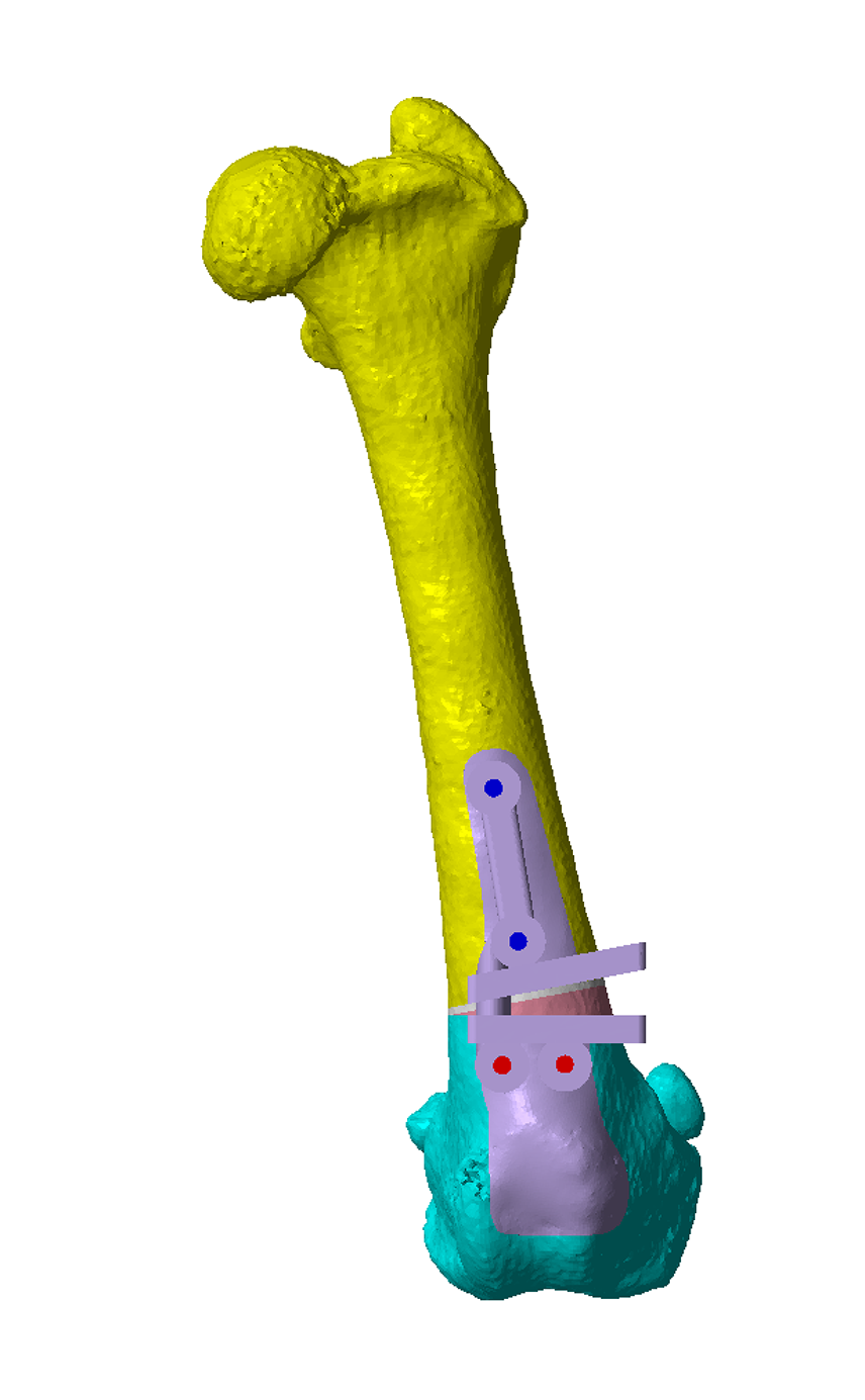
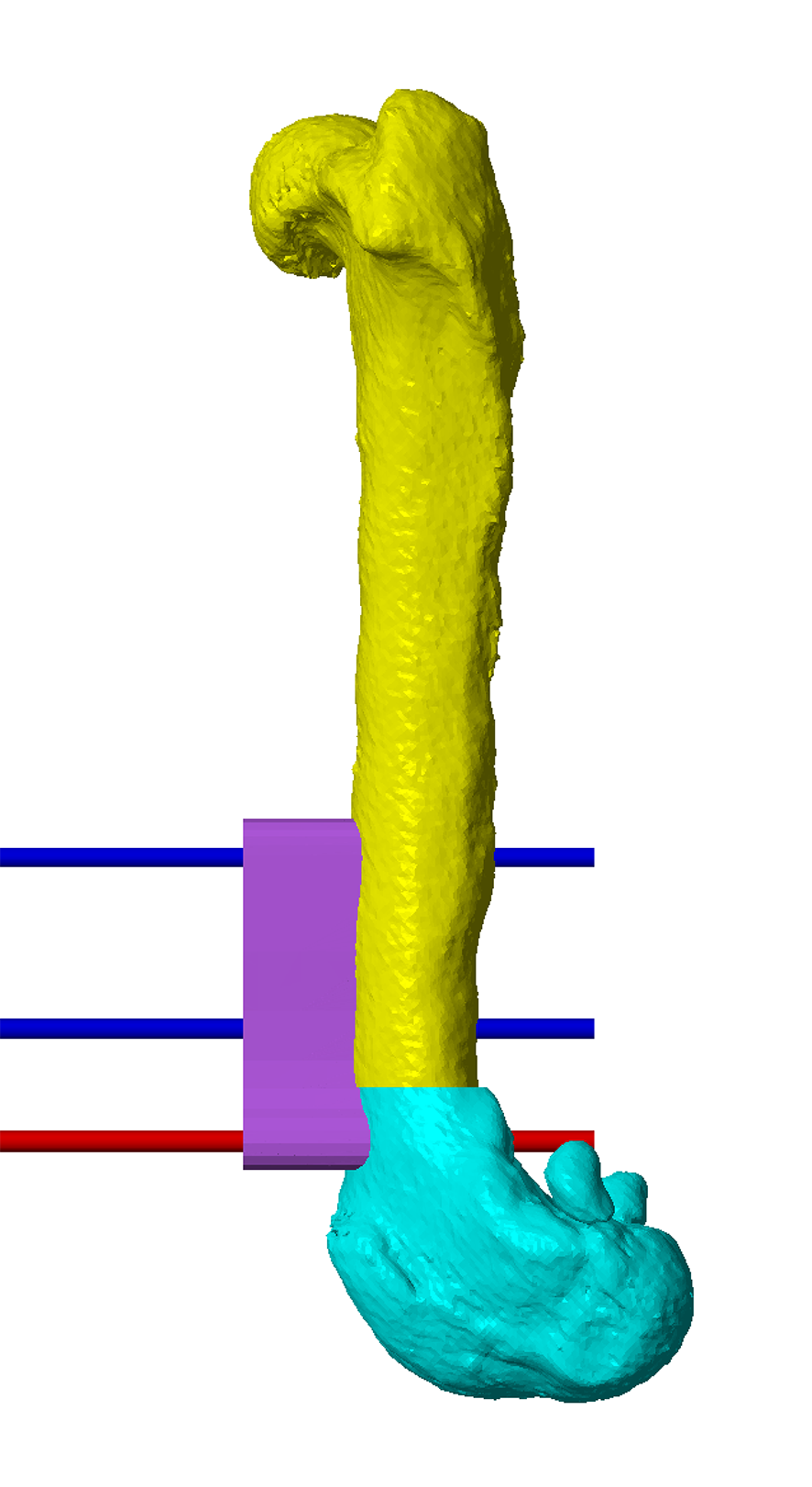
Figure 4 – The virtual osteotomy guide in-situ. The blue and red cylinders represent planned trajectories of Ellis pins which secure the osteotomy guide to the bone. These are orientated such that, when aligned in parallel by a reduction guide, optimal alignment of the osteotomy fragments results. In this case realignment in uniplanar, but concurrent correction of multiplanar deformities can be achieved in the same way. The planned closing wedge is shown in white / pink; the two flat planes represent guide surfaces for an oscillating saw blade. The small connecting bars between the osteotomy planes maintain integrity of the guide during application, but are removed after the Ellis pins are placed.
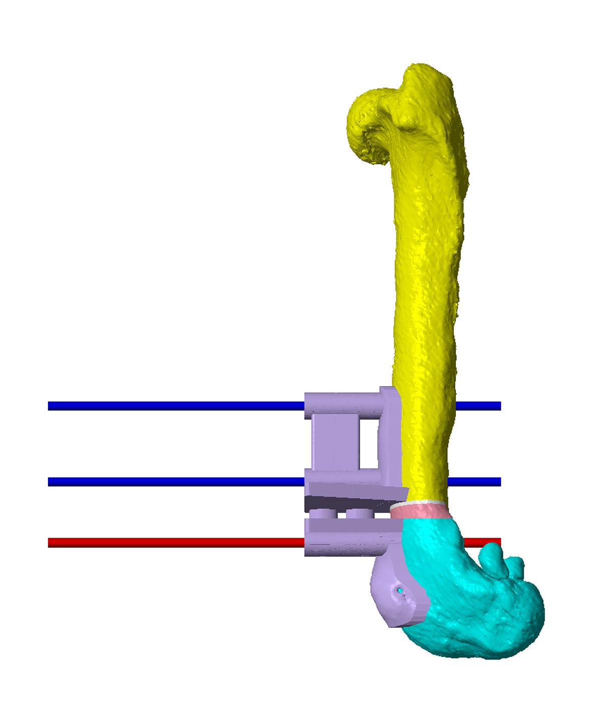
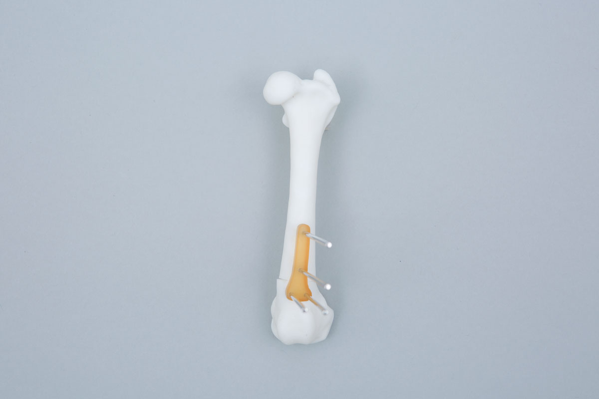
Figure 5 – The femur and osteotomy guide have been 3D printed. The osteotomy guide is in-situ and attached with Ellis pins. The osteotomies are made with the oscillating saw blade maintained parallel to, and in contact with, the guide surfaces (slotted guides can also be made, although are more bulky in small patients and limit the angle of attack of the blade).
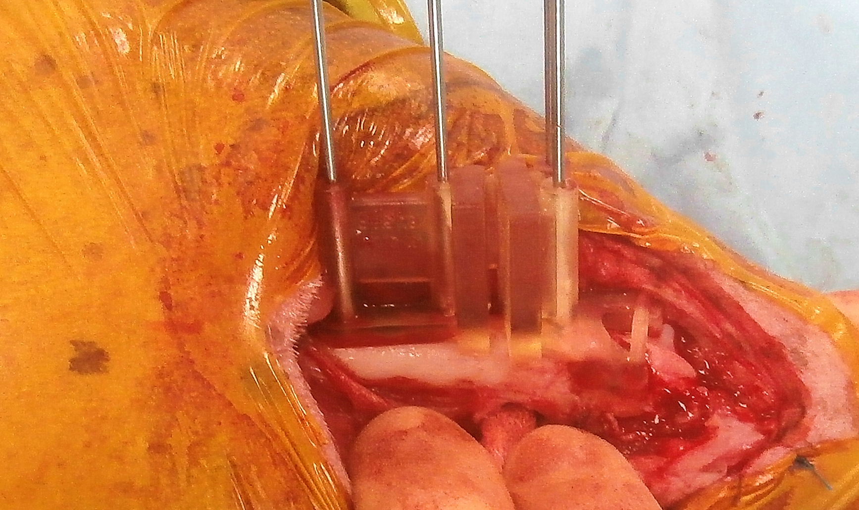
Figure 6 – The osteotomy guide has been removed, leaving the Ellis pins in place.
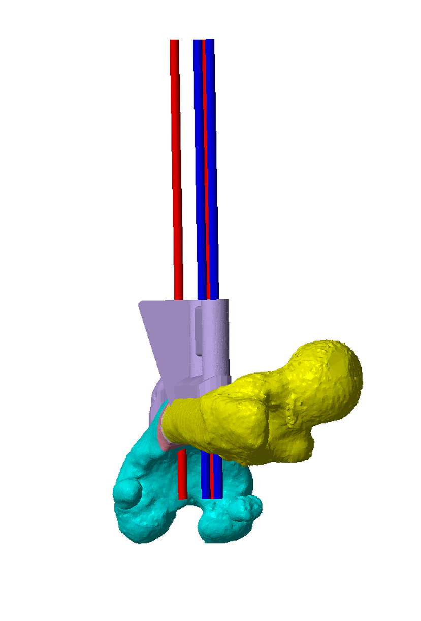
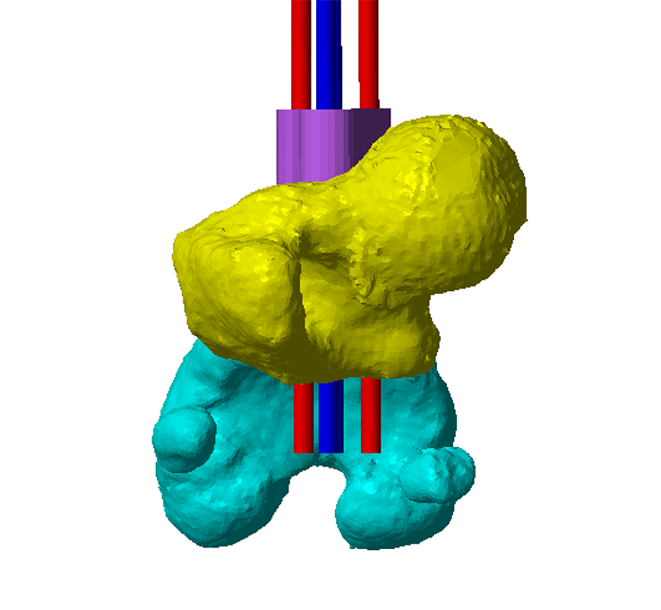
Figure 7 – When the Ellis pins are aligned in parallel by the reduction guide the proximal and distal osteotomy fragments are aligned as planned in the CAD.
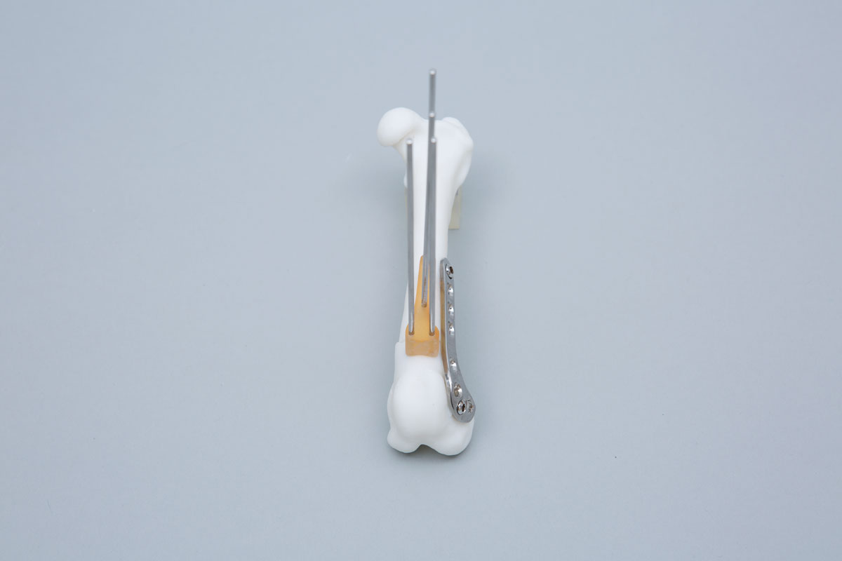
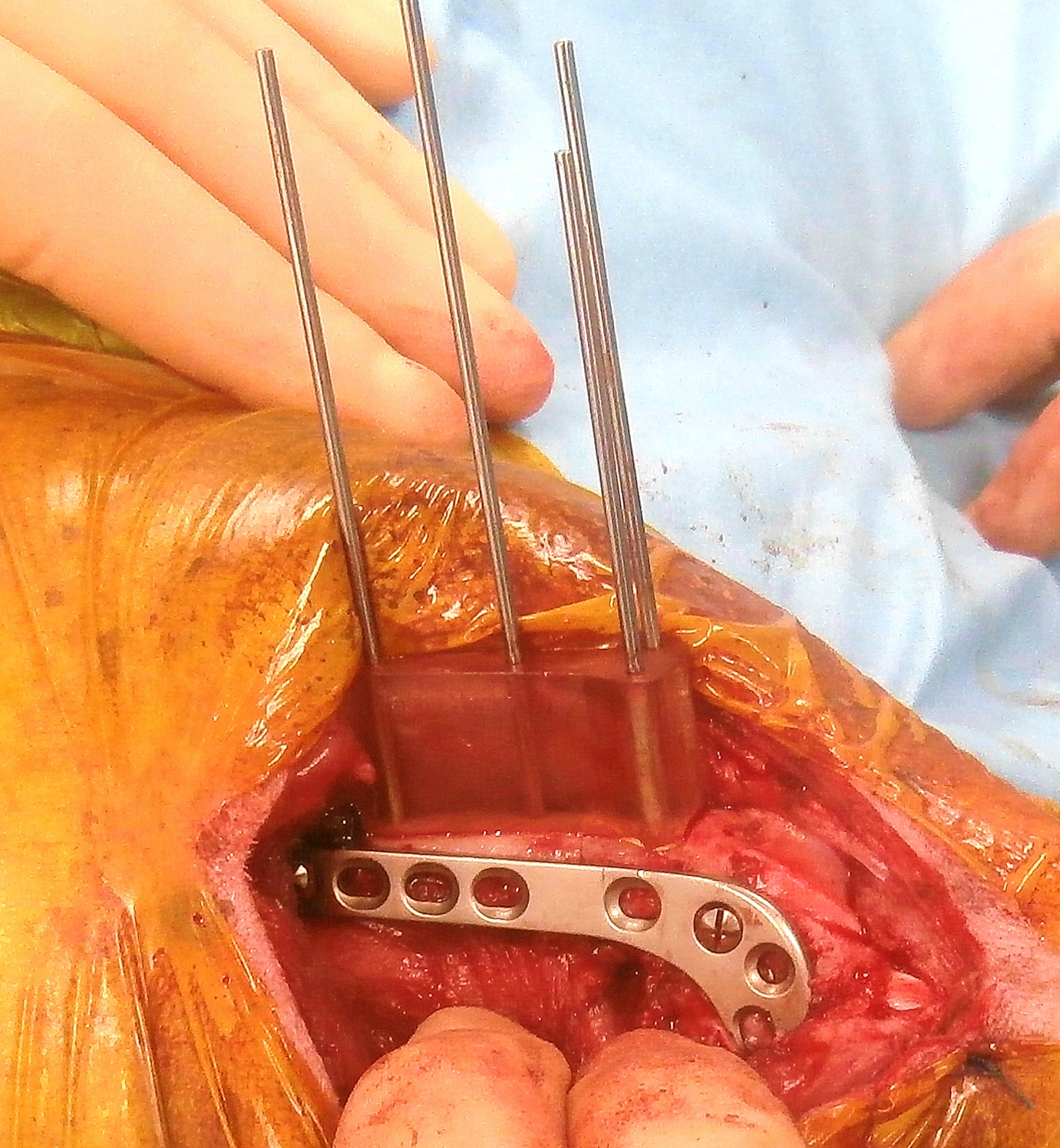
Figure 8 – The reduction guide maintains planned alignment whilst a plate is applied. The position of the Ellis pins and guide is planned to leave space for the plate which can be precontoured to a 3D printed model of the post-reduction radius.
Figure 9 – Pre- and post-operative CT. Femoral varus angle has reduced from 17° to 3°.
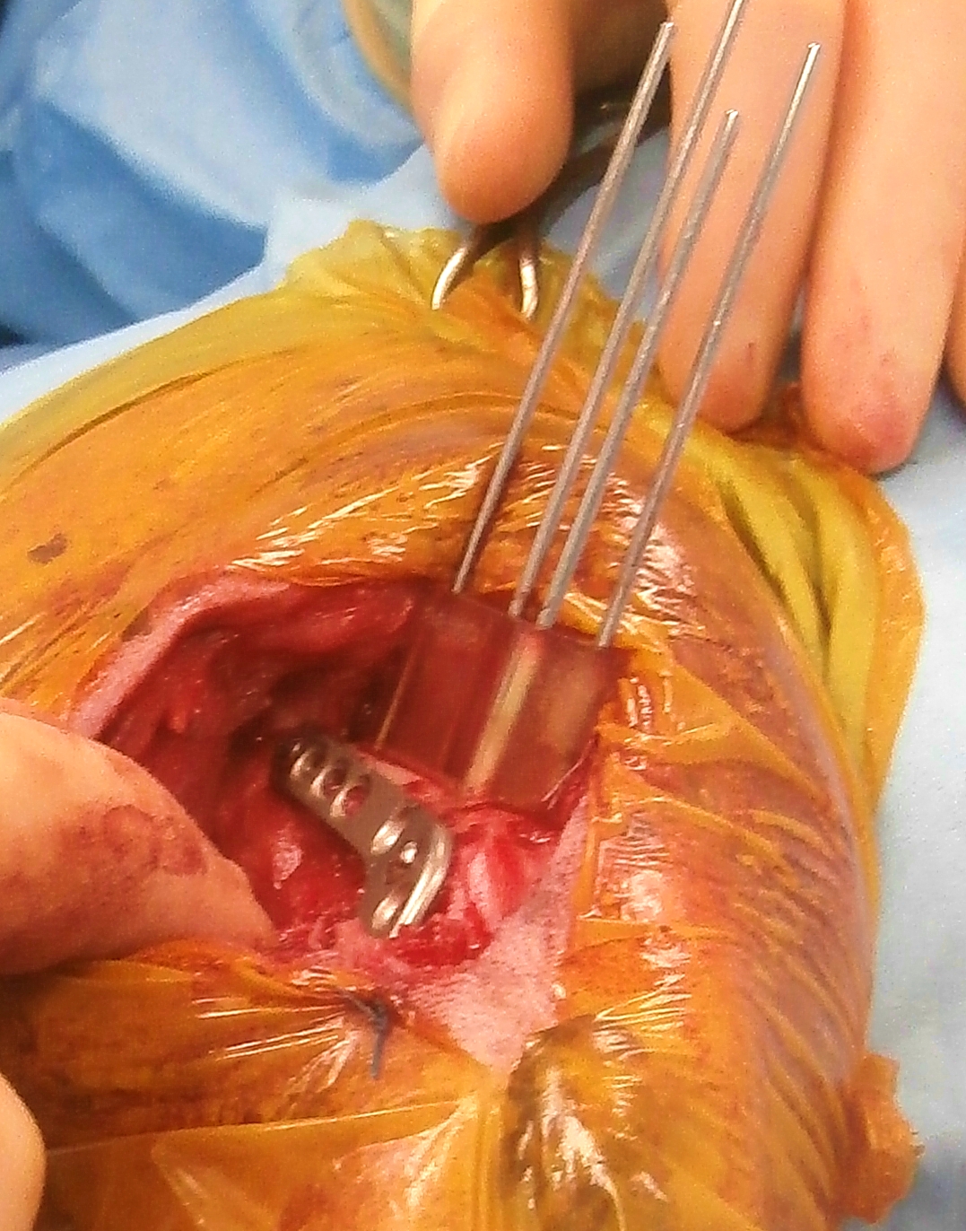
Figure 10 – The osteotomy guide in situ and attached with four Ellis pins. The design of the distal contact surface of the guide has been altered to avoid an area of cortical remodelling affecting the abaxial aspect of the lateral trochlear ridge A and B). The reduction guide has reduced the osteotomy and maintains alignment whilst a plate is applied laterally.
Surgical planning and 3D printing
The overall cost includes 3D data processing, CAD virtual osteotomy planning and design of osteotomy and reduction guides, and 3D printing.
If required CAD-based quantification of femoral varus and torsion is also included in the total cost, or these values can be surgeon-specified.
- Please note should this be requested and DFO prove not to be indicated a fee of £55 will be invoiced to cover data processing and CAD time.
- CAD-based quantification of femoral varus and torsion can be requested as a stand-alone service for the same fee - please upload DICOMs via the "Preliminary Assessment" page and specifiy this service.
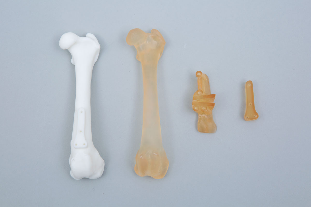
For most cases the following models and guides are printed (Figure 11) –
- Pre-op femur – to practice osteotomy guide fit (usually in autoclavable resin)
- Post-op femur usually with reduction guide footprint in-situ – for plate precontouring (usually in white non-autoclavable resin)
- Osteotomy and reduction guides (autoclavable and biocompatible resin)
Please see Price Guide for additional information
Figure 11 – Guides and models printed in most cases (alternatives can be surgeon-specified). The osteotomy and reduction guides are printed in biocompatible, autoclavable plastic (A). The pre-operative radius is printed in high-temperature plastic (B) - osteotomy guide fit can be practised before surgery, and the model then autoclaved. The post-operative bone is printed in white plastic (non-autoclavable) to permit pre-contouring of the planned primary bone plate (C). In most cases the bone is printed with the footprint of the reduction guide in-situ to facilitate pre-contouring in the appropriate position. Since the reduction guide usually occupies the space required by a second plate, if specific this can be made removable such that both plates can be precontoured.
References
1. Swiderski JK, Palmer RH: Long-term outcome of distal femoral osteotomy for treatment of combined distal femoral varus and medial patellar luxation: 12 cases (1999-2004). J Am Vet Med Assoc 231:1070-1075, 2007.
2. Brower BE, Kowaleski MP, Peruski AM, et al: Distal femoral lateral closing wedge osteotomy as a component of comprehensive treatment of medial patellar luxation and distal femoral varus in dogs. Veterinary and Comparative Orthopaedics and Traumatology (VCOT) 30:20-27, 2017.
3. Oxley B, Gemmill TJ, Pink J, et al: Precision of a novel computed tomographic method for quantification of femoral varus in dogs and an assessment of the effect of femoral malpositioning. Vet Surg 42:751-758, 2013.
4. Barnes DM, Anderson AA, Frost C, et al: Repeatability and Reproducibility of Measurements of Femoral and Tibial Alignment Using Computed Tomography Multiplanar Reconstructions. Veterinary Surgery 44:85-93, 2015.
5. Olimpo M, Piras LA, Peirone B, et al: Comparison of osteotomy technique and jig type in completion of distal femoral osteotomies for correction of medial patellar luxation. An in vitro study. Veterinary and Comparative Orthopaedics and Traumatology (VCOT) 30:28-36, 2017.
©Copyright 2017 - Vet 3D | Terms & Conditions | Cookie Policy