- Login
- Sign Up
- Online referral form
This site is optimised for modern web browsers, and does not fully support your version of Internet Explorer, some sections of the website may not work correctly such as web forms


Antebrachial Deformities
Probably the most commonly encountered examples are developmental antebrachial deformities associated with chondrodysplasia (for example the Shih Tzu, Basset hound, springer spaniel and several terrier breeds).
Surgical management of developmental antebrachial deformities is challenging for several reasons –
- The complex nature of the conformational abnormalities present (multiplanar with a translational component; occasionally biapical).
- The frequent presence of concurrent elbow and carpal pathologies including -
- Radial head subluxation; this is a key contributory factor to the conformational abnormality (usually resulting in an intra-articular CORA) - as well as a potential cause of persistent lameness.
- Humeroulnar incongruity.
- Antebrachiocarpal joint laxity.
- The technical difficult of fully quantifying every component of the deformity, as well as the lack of breed specific normal values as a target for correction.
- The bilateral presentation which precludes the use of a normal contralateral limb as a template for optimal realignment.
- The technical difficulty of accurately reproducing the planned correction in theatre, especially given the often marked deformities of small bones. Specific challenges include -
- Accurate identification of the position of the CORA.
- Appropriate positioning of the osteotomies relative to the CORA.
- Achieving correct saw blade orientation for each osteotomy such that planned realignment results in reduction, especially for a closing wedge.
- Reduction about the planned angulation correction axis.
- Maintenance of accurate reduction whilst fixation is applied.
The most appropriate surgical strategy is to some degree dependent on the precise nature of the presenting problem, but usually comprises one or two radial and ulnar osteotomies, with either acute deformity correction (usually with plate fixation) or progressive correction with circular external skeletal fixation.
Virtual Surgical Planning
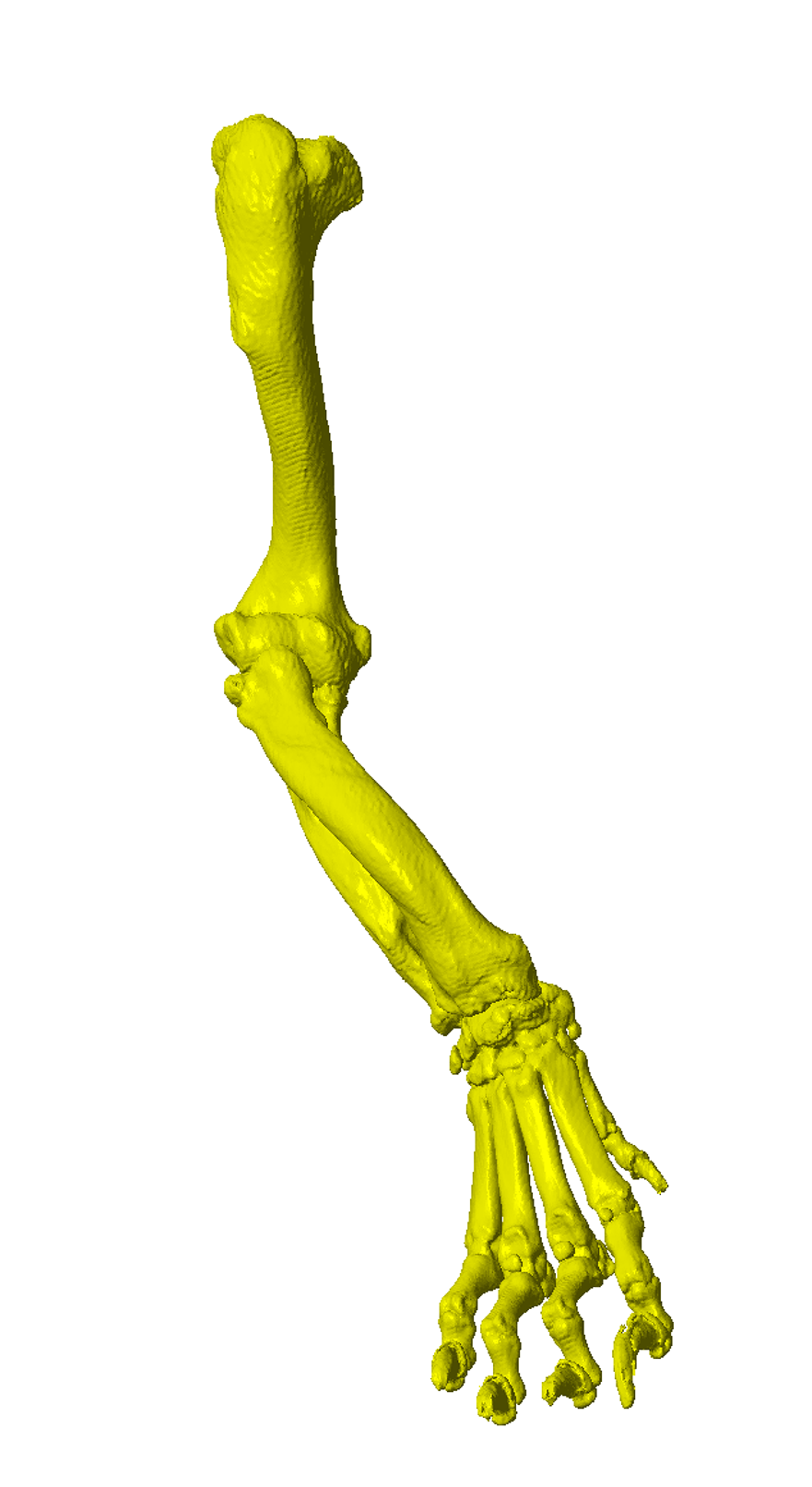
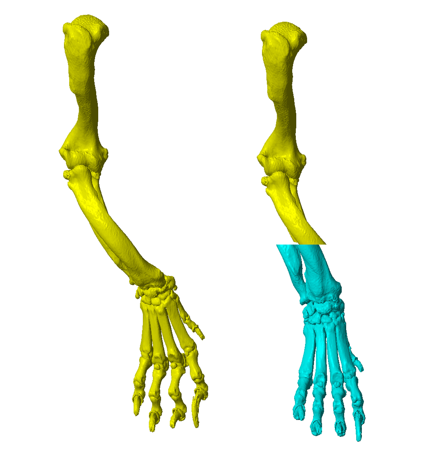
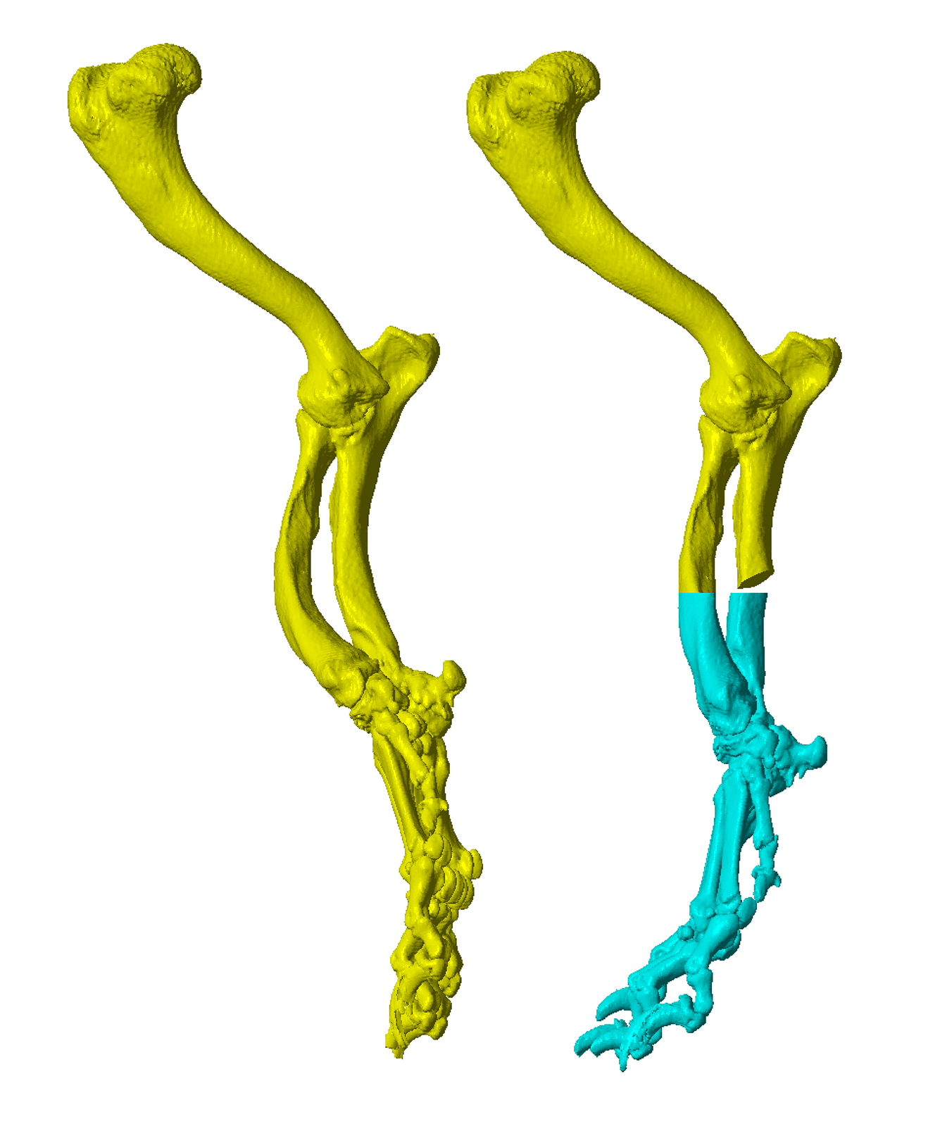
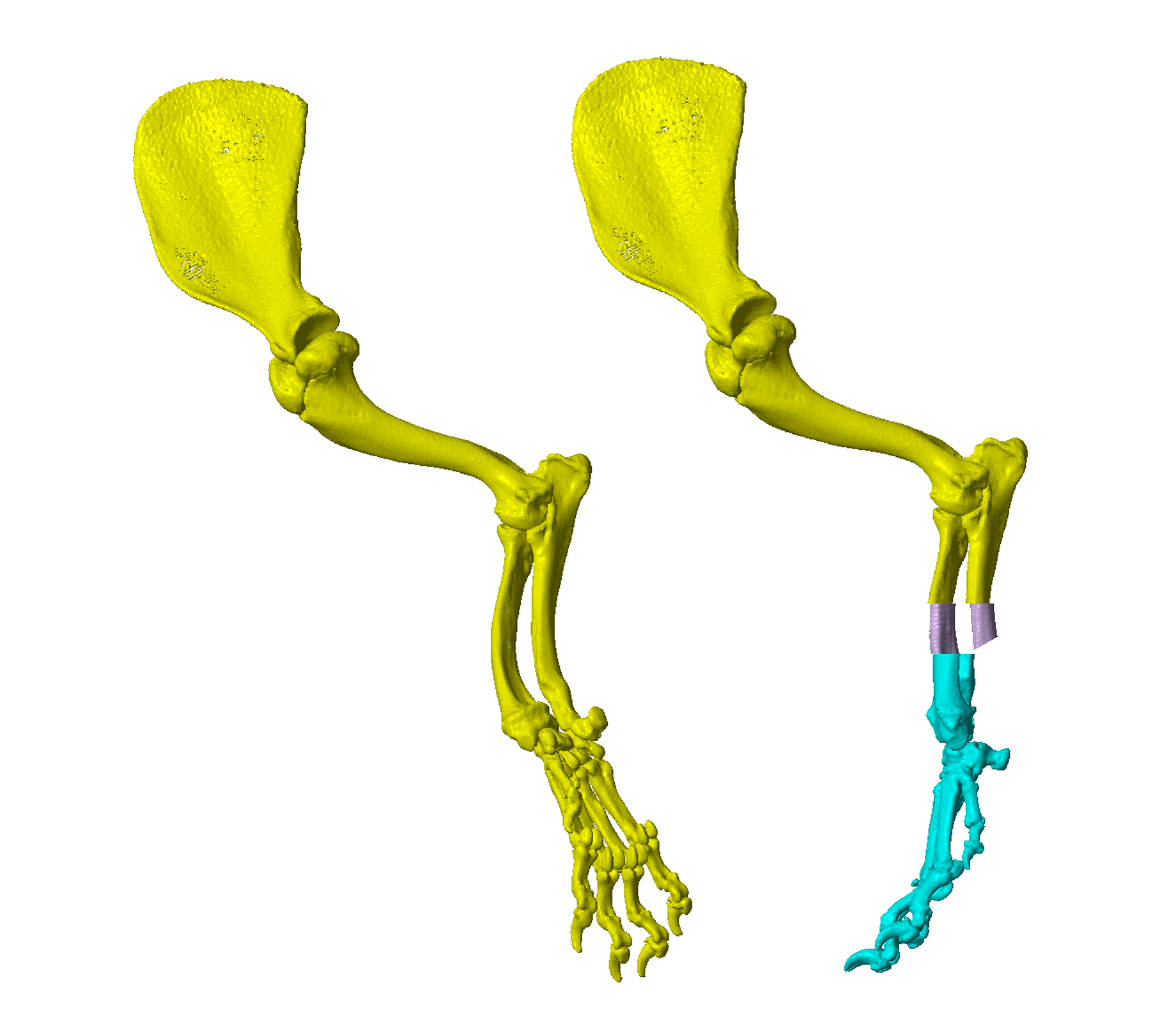
CT data is processed to obtain 3D representations of the bones of the affected thoracic limb (Figure 1). This 3D model can be manipulated within CAD software. The deformity can be visualised, virtual osteotomies performed, and the proximal and distal segments of the bone reoriented with six degrees of freedom to achieve optimal antebrachial alignment (Figure 2). Two methodologies can be applied –
- Osteotomy position(s), and precise triplanar angular and translational corrections can be made based on CORA position and deformity quantification (vs. optimal) from prior analysis of CT data.
- Osteotomy position(s) are determined by visual assessment of the point(s) of maximal deformity, and the distal segment visually reoriented to yield appropriate overall antebrachial conformation.
In practice, surgeon preference determines the approach adopted, although in most cases virtual osteotomies and distal segment reorientation are finalised during live screen-sharing. In this way, the surgeon can control and modify the virtual surgical procedure until an optimal outcome is achieved.
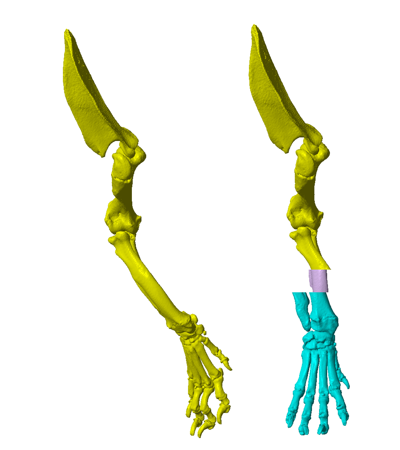
Figure 1 – A CAD virtual 3D representation of the right antebrachium of a four year old male Shih Tzu weighing 8kg. Within the CAD software the model can be manipulated in all planes and viewed from any perspective.
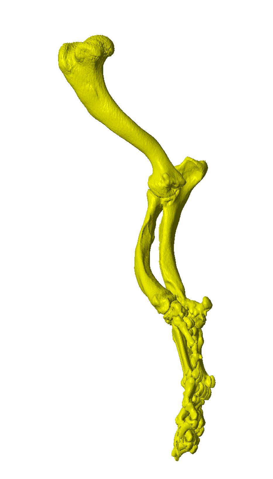
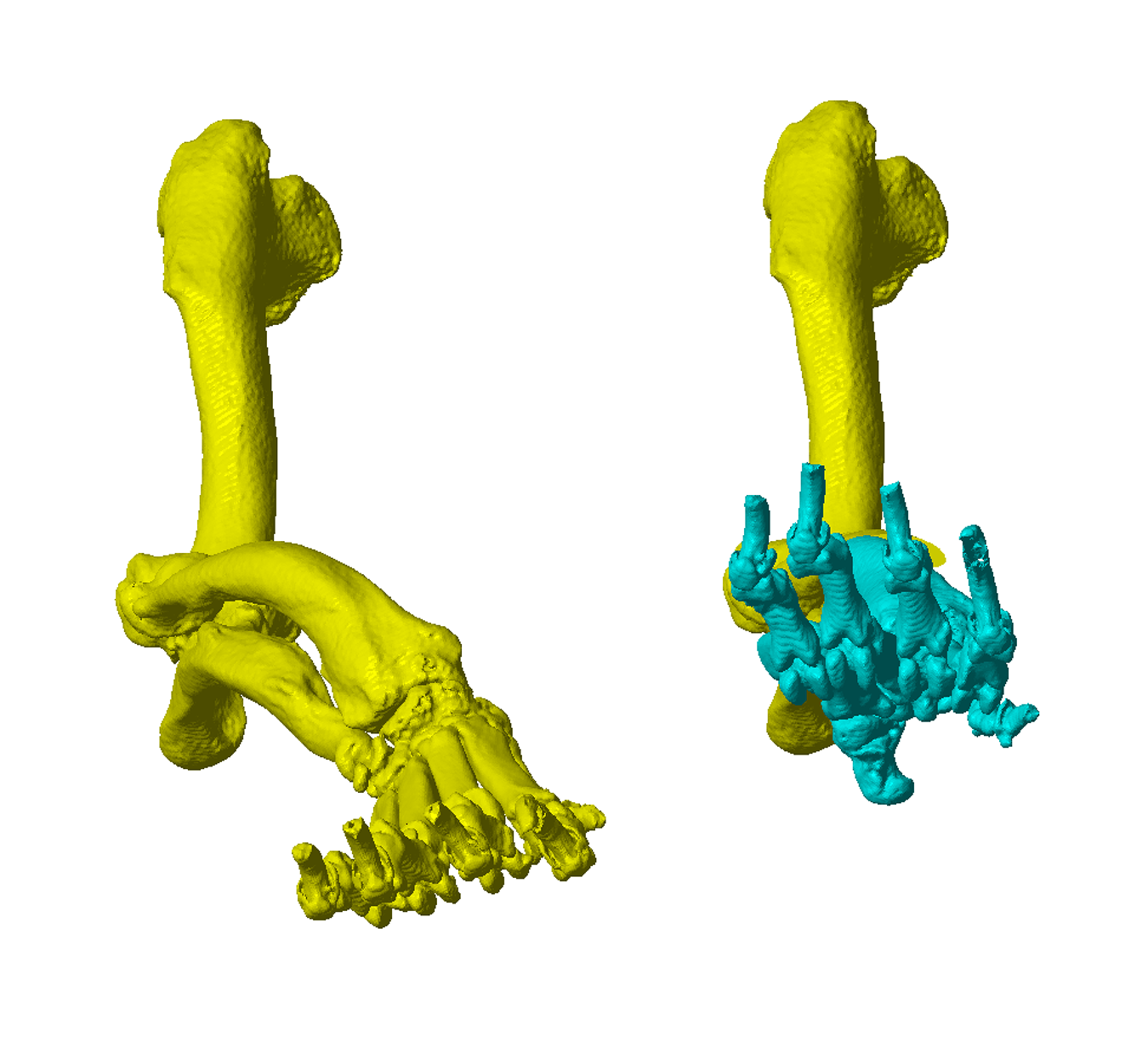
Figure 2 – A virtual radial osteotomy has been performed. The distal limb has been realigned in all three planes, with torsional and frontal plane corrections of the greatest magnitude.
Osteotomy and Reduction Guide Design
Once osteotomy position and distal segment reorientation are determined, osteotomy and reduction guides can be created.
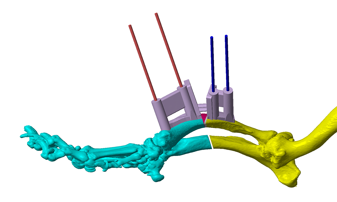
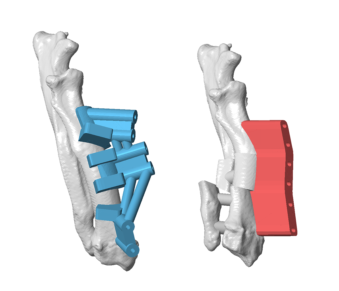
Key features on the osteotomy guide include (Figure 3) -
- Oscillating saw guide planes (orientated such the precise wedge required to achieve the plannned limb realignment is removed)
- Channels for Ellis pins (orientated such that when aligned in parallel by the reduction guide planned orientation and reduction of the proximal and distal segments is achieved)
- A contact surface which precisely reflects that of the radial cortex to which it will be applied (such that the guide therefore fits only in a specific, unique location, thereby precisely defining the relative positions and orientations of saw guide surfaces and Ellis pin channels).
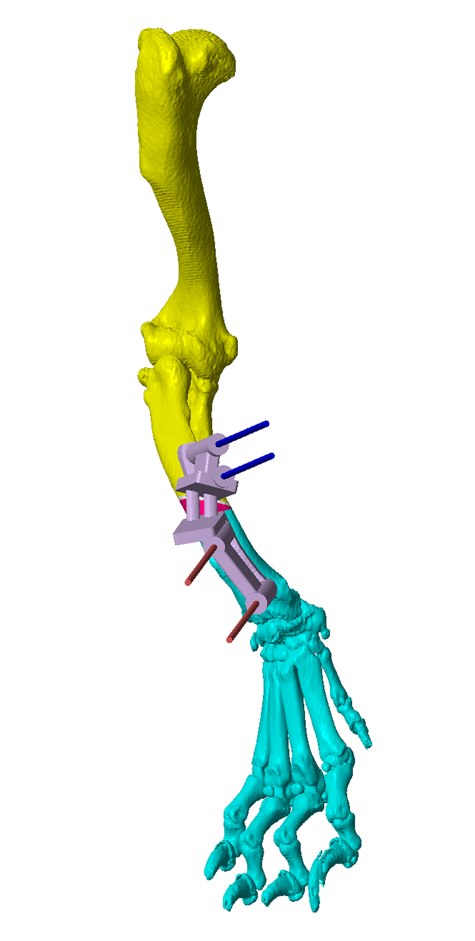
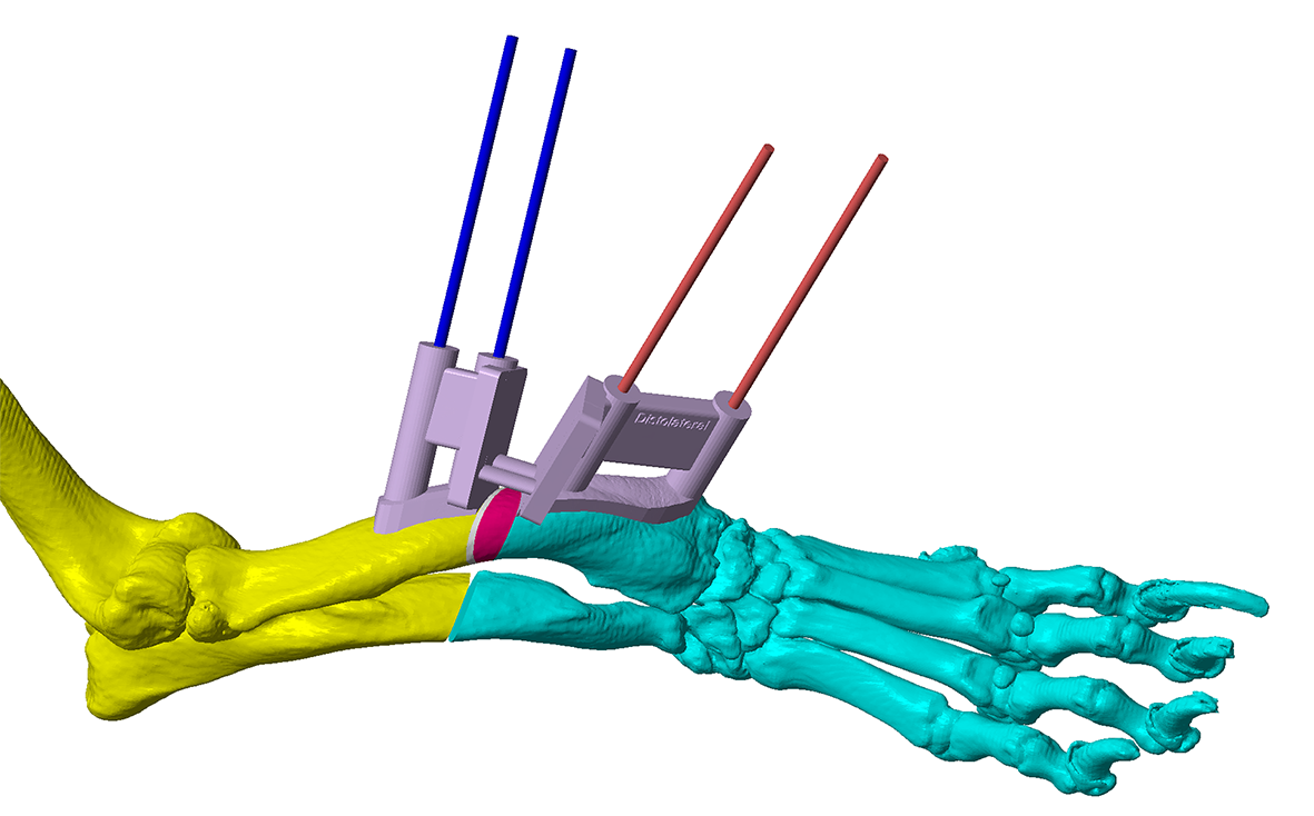
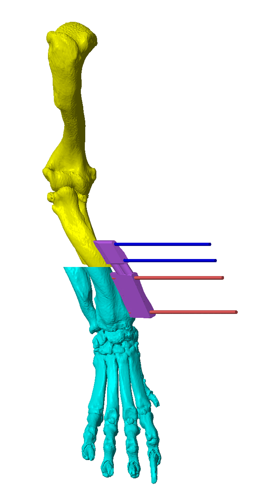
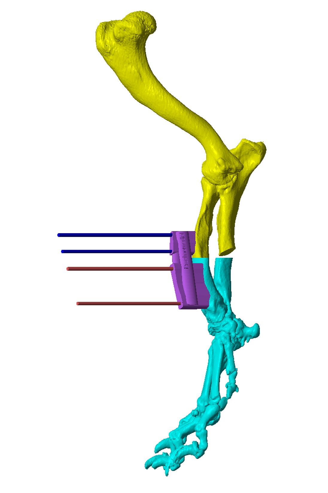
Figure 3 – The virtual osteotomy guide in-situ. The blue and red cylinders represent planned trajectories of Ellis pins which secure the osteotomy guide to the bone. These are orientated such that, when aligned in parallel by a reduction guide, optimal alignment of the osteotomy fragments results. The planned cuneiform closing wedge is shown in white / pink; the two flat planes represent guide surfaces for an oscillating saw blade. The significant torsional correction is apparent from the offset between the two sets of Ellis pin trajectories. The small connecting bars between the osteotomy planes maintain integrity of the guide during application, but are removed after the Ellis pins are placed.
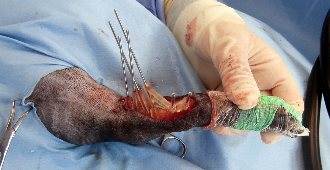
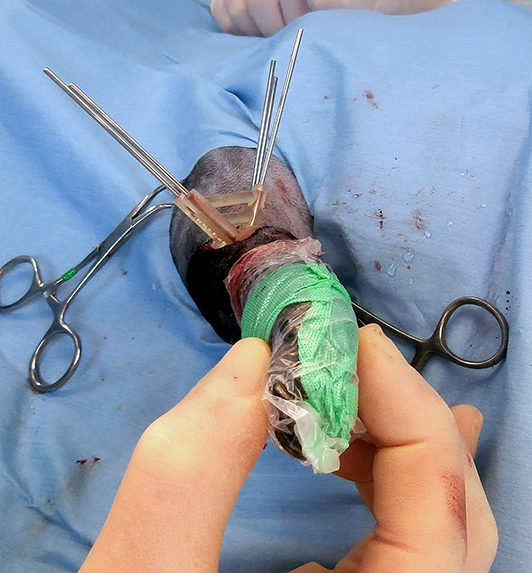
The osteotomies are made with an oscillating saw aligned to the guide planes (Figure 4). The guide is then removed, but the Ellis pins left in-situ (Figure 5). The original trajectories of the pins are designed such that when these are aligned in parallel by the reduction guide the radius is reduced to the pre-planned orientation (Figure 6). The guide maintains reduction whilst a plate is applied (usually cranially; the plate can be precontoured to a 3D printed model of the post-reduction radius) (Figure 7). The Ellis pins and guide are removed; a second plate can be applied medially if necessary. Figure 8 shows post-operative radiographs. In this case the surgeon opted for a more distal ulnar osteotomy, and chose to place two plates. Achieved alignment corresponded well to that planned; although there was mild medial translation of the paw relative to the elbow, paw orientation was much improved and procurvatum normalised (resolving buckling-over on the carpus).
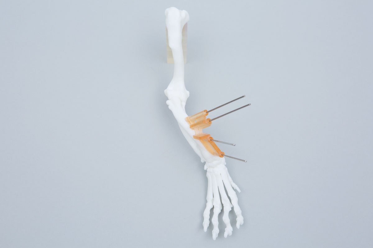
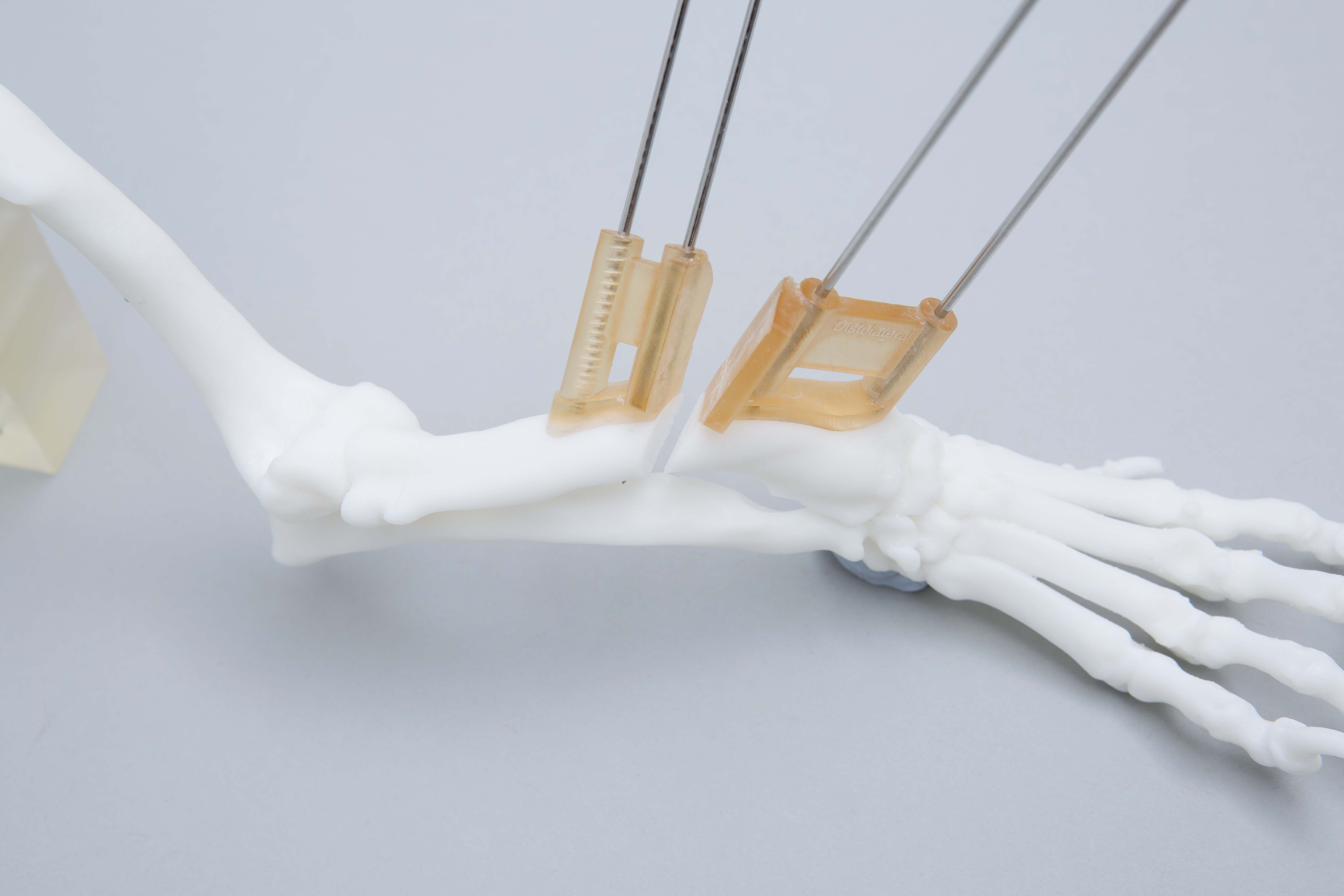
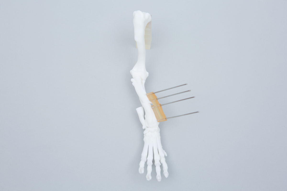
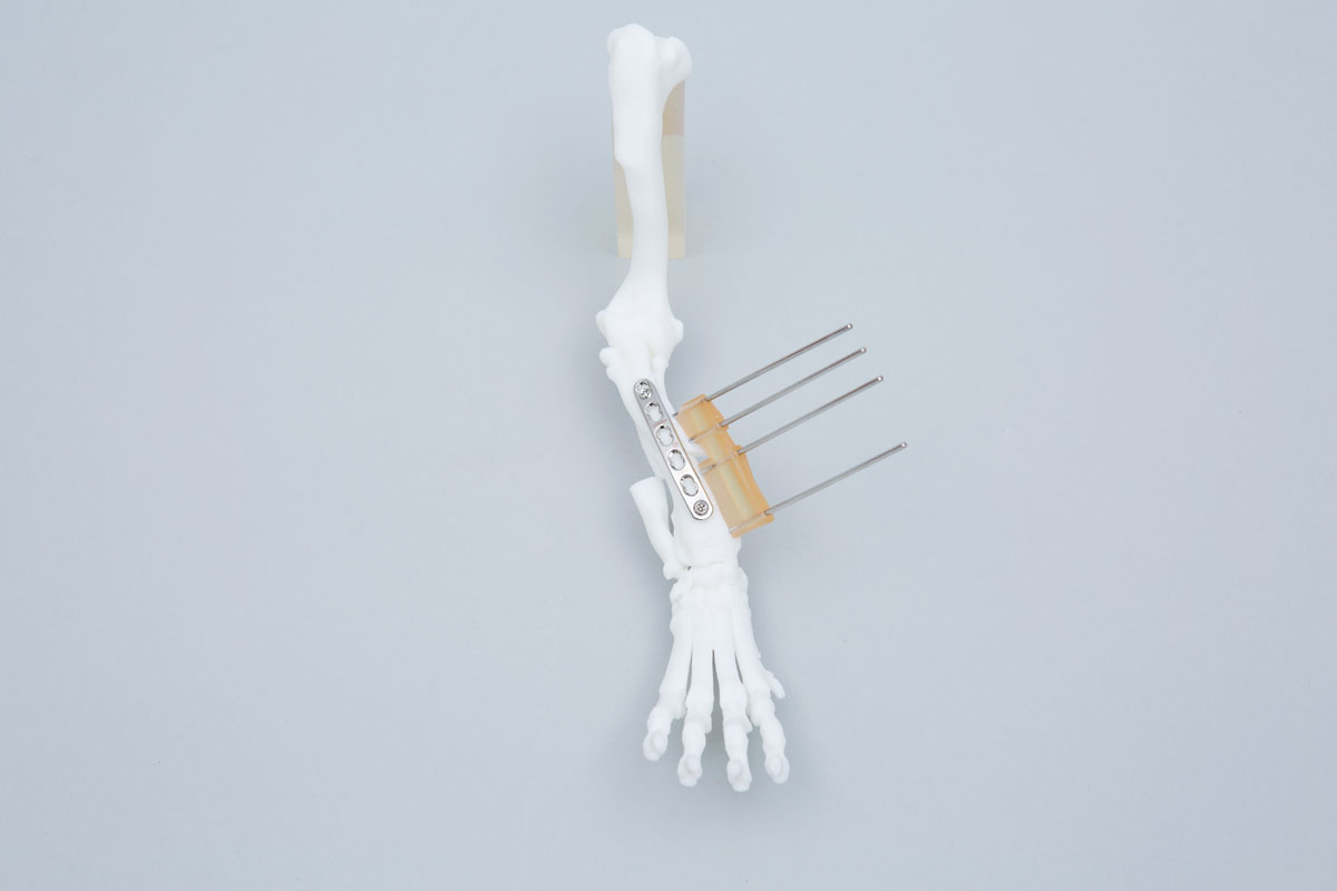
Figure 4 – A 3D printed bone model with the osteotomy guide in-situ and attached with Ellis pins. The osteotomies are made with the oscillating saw blade maintained parallel to, and in contact with, the guide surfaces (slotted guides can also be made, although are more bulky in small patients and limit the angle of attack of the blade).
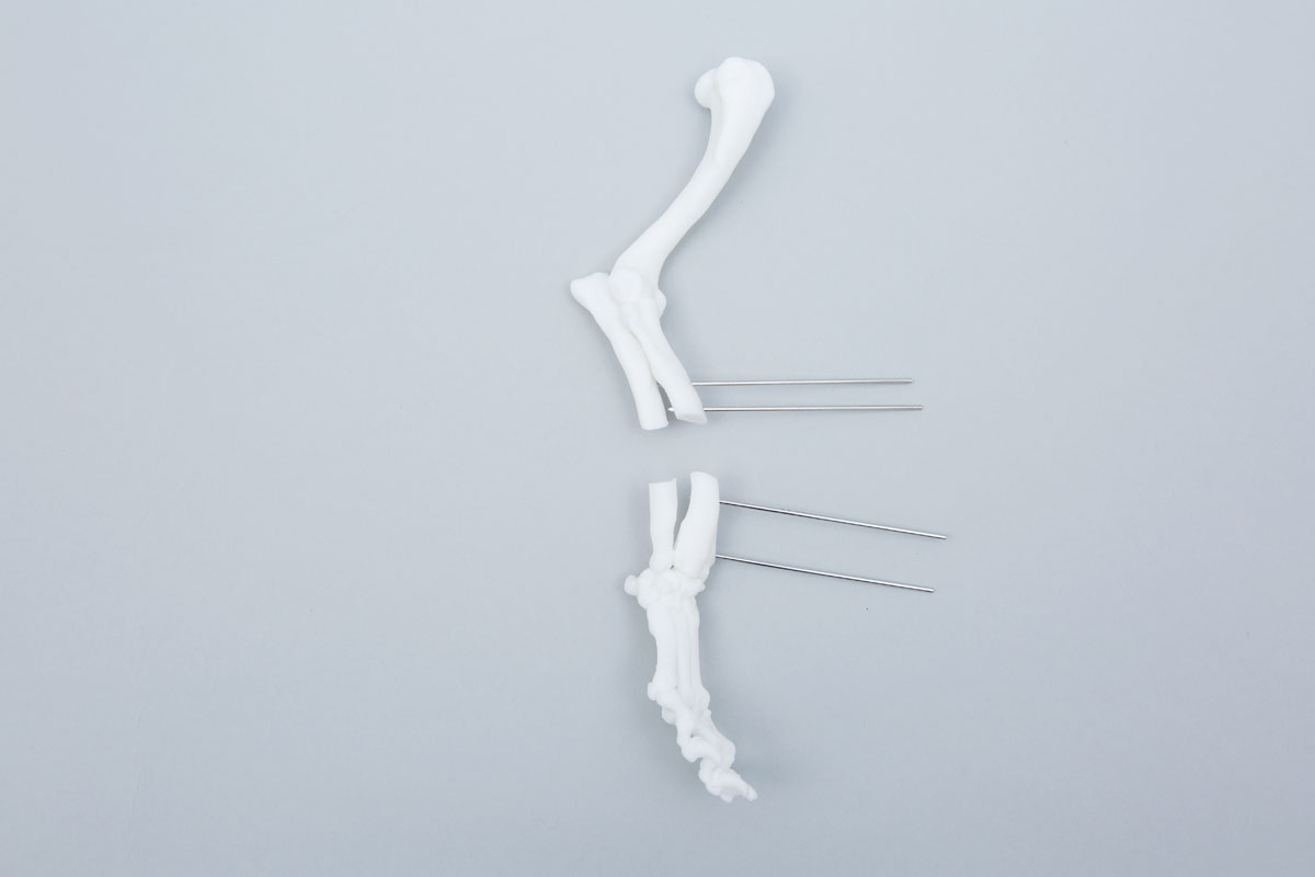
Figure 5 – The osteotomy guide has been removed, leaving the Ellis pins in place.
Figure 6 – When the Ellis pins are aligned in parallel by the reduction guide the proximal and distal osteotomy fragments are aligned as planned in the CAD.
Figure 7 – The reduction guide maintains planned alignment whilst a plate is applied. The position of the Ellis pins and guide is planned to leave space for the plate which can be precontoured to a 3D printed model of the post-reduction radius.
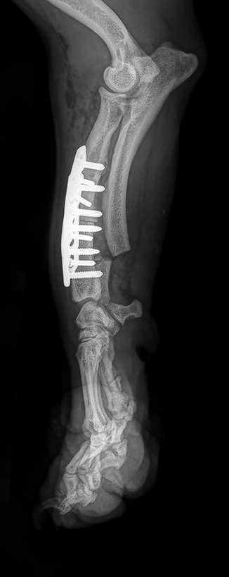
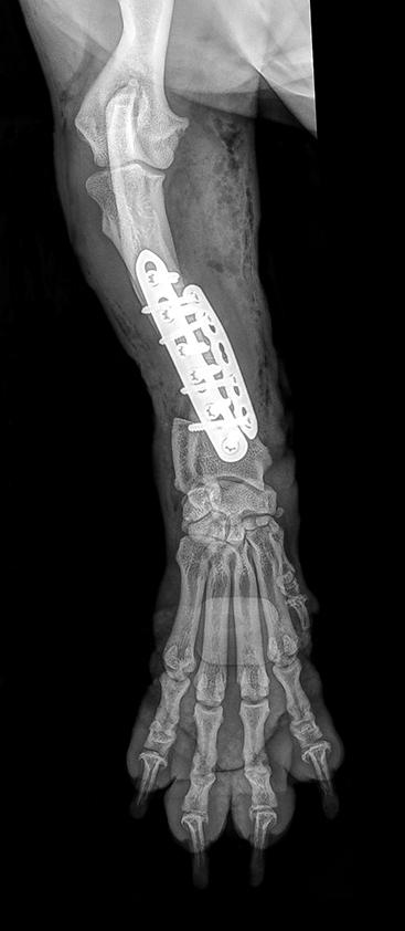
Figure 8 – Post-operative radiographs showing close approximation of achieved to planned final alignment. Images coutesy Stephen Kalff (Fitzpatrick Referrals).
Although most antebrachial deformities are strictly biapical, the majority can be adequately addressed with a single radial / ulnar osteotomy since, as in the above case, the degree of residual translation is clinically acceptable. In some cases however biapical corrections are necessary and can also be modelled (Figure 9). Intra-operative images are shown in Figure 10, and post-operative alignment and volume rendered CT images in Figure 11. The mild residual carpus valgus is the result of antebrachiocarpal joint laxity, an important parameter to quantify pre-operatively since this will obviously persist after bone deformity correction.
The processes of virtual surgical planning and guide design are generally very similar for other forms of deformity correction.
Figure 9 – A CAD virtual 3D representation of the right antebrachium of an 11 month old female crossbreed dog weighing 7kg. Marked medial translation of the paw is present as well as significant torsional and frontal plane deformities; realignment was planned with proximal and distal radial osteotomies (A and B). Osteotomy and reduction guides designed to achieved the planned alignment (C).
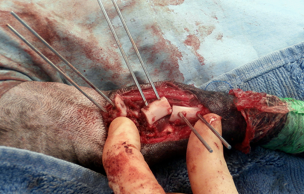
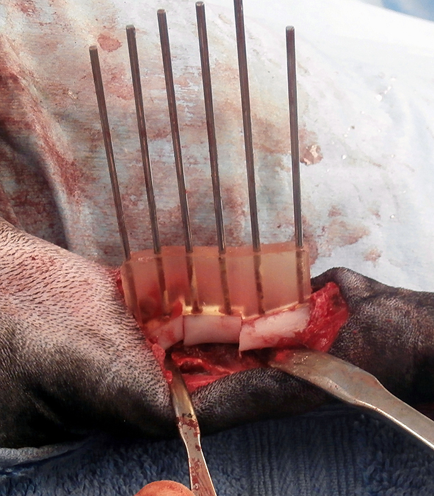
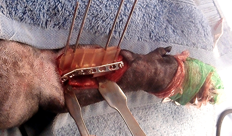
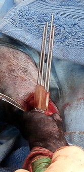
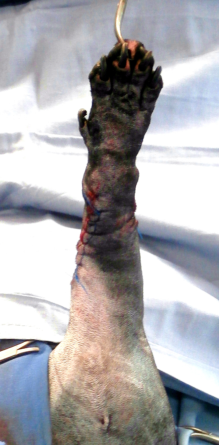
Figure 10 – Intra-operative images. The osteotomy has been applied to the craniomedial aspect of the radius and its planned position identified by manual and visual assessment of optimal fit to the underlying cortex. Once positioned the guide is attached with Ellis pins (A and B). The osteotomies have been completed and the osteotomy guide removed (C). The reduction guide has been applied over the Ellis pins, reducing all three osteotomy fragments and maintaining alignment whilst a pre-contoured 2mm LCP is applied adjacent to the guide (D, E and F).
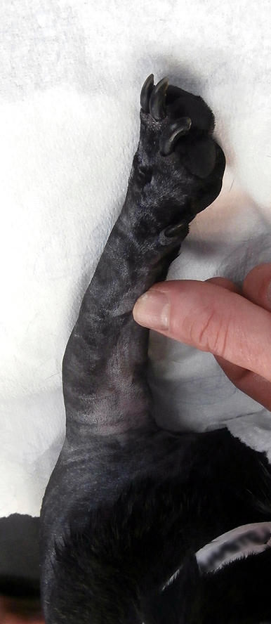
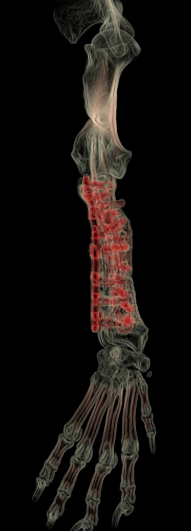
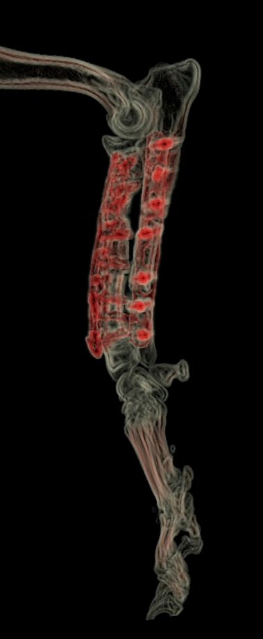
Figure 11 – Comparison between pre-operative (A) and immediate post-operative (B) limb alignment. Post-operative volume rendered CT images (C and D). Mild apparent carpal valgus is evident which is not apparent in the post-operative photograph. This is the result of antebrachiocarpal joint laxity resulting from chronic abnormal joint loading, and will result in lateral paw deviation during weight-bearing. It is important that the degree of ABC joint laxity is assessed pre-operatively since if severe residual functional valgus may significantly affect overall function and comfort despite appropriate deformity correction. In such cases combined deformity correction and pancarpal arthrodesis should be considered from the outset.
3D Printing
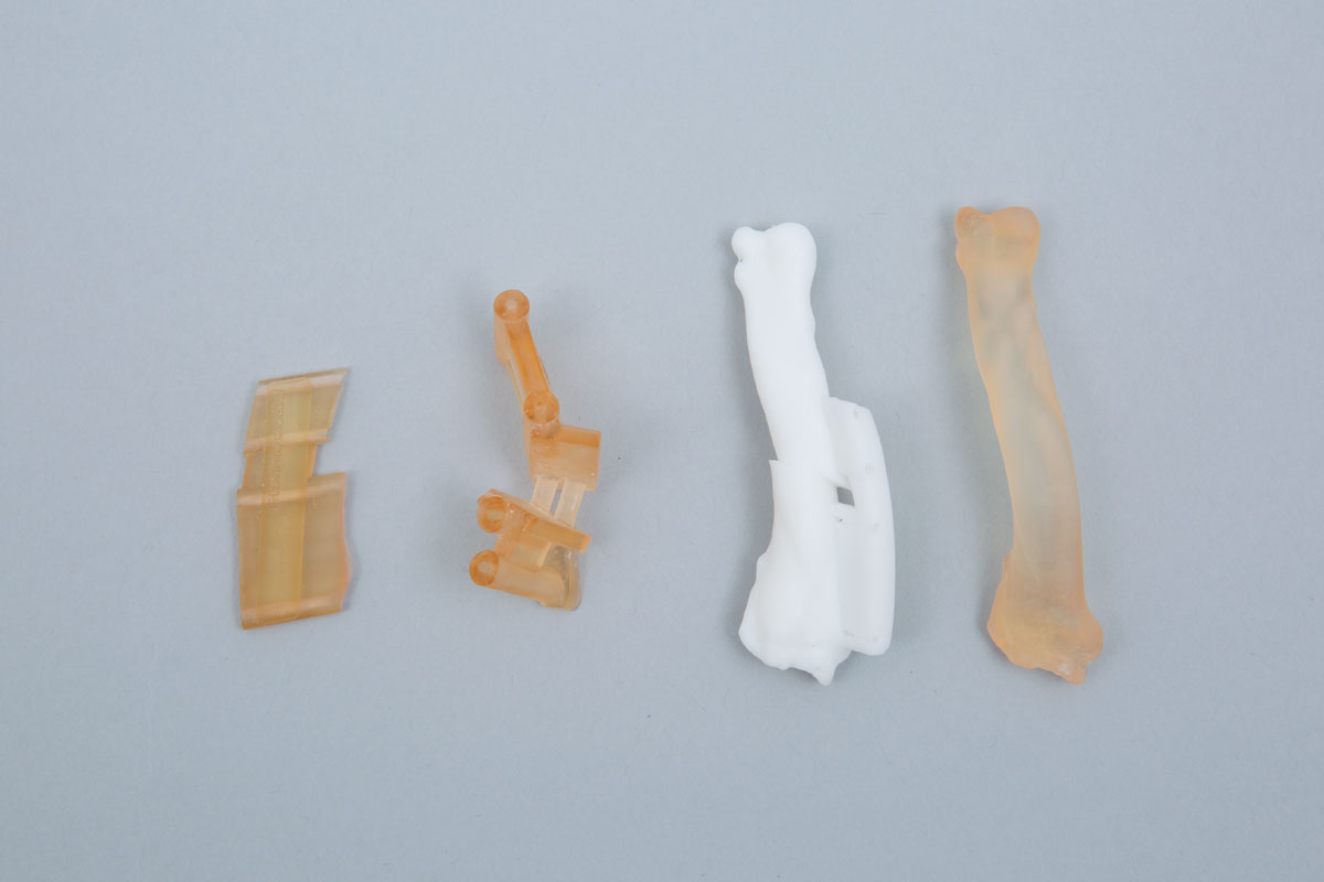
For most cases the following models and guides are printed (Figure 12) –
- Pre-op radius or usually bone segment (antebrachium with elbow and carpus including base of metacarpals) - autoclavable – osteotomy guide fit practice.
- Post-op radius or usually bone segment (as above, with reduction guide footprint in-situ) - white non-autoclavable resin - for plate pre-contouring.
- Osteotomy and reduction guides (autoclavable and biocompatible resin).
Please see Price Guide for additional information
Figure 12 – Guides and models printed in most cases (alternatives can be surgeon-specified). The osteotomy and reduction guides are printed in biocompatible, autoclavable plastic (A). The pre-operative radius is printed in high-temperature plastic (B). Osteotomy guide fit can be practised before surgery; the model can then autoclaved and therefore available in theatre. The post-operative bone is printed in white plastic (non-autoclavable) to permit pre-contouring of the planned primary bone plate. In most cases the bone is printed with the footprint of the reduction guide in-situ to facilitate pre-contouring in the appropriate position. Since the reduction guide usually occupies the space required by a second plate, if specific this can be made removable such that both plates can be precontoured.
Intellectual Property Office Registered Design numbers 6003205 and 6003207
©Copyright 2017 - Vet 3D | Terms & Conditions | Cookie Policy