- Login
- Sign Up
- Online referral form
This site is optimised for modern web browsers, and does not fully support your version of Internet Explorer, some sections of the website may not work correctly such as web forms


Fractures
Patient-specific guides can be used to position Ellis pins in the major proximal and distal fracture fragments such that anatomic realignment results following application of a reduction guide. This approach can be applied durimg both MIPO and ORIF.
Minimally invasive plate osteosynthesis
The development of minimally invasive plate osteosynthesis (MIPO) has been driven by an increasing recognition of the importance of fracture site biology to bone healing.Preservation of local vascularity is a key principle and is maximised by reduced dissection at the fracture site,with other effects such as minimisation of disruption to the fracture haematoma also likely to be important. These potential benefits must be balanced against the greater technical difficulty of MIPO, most notably achieving optimal spatial orientation of the major proximal and distal fracture fragments without visualisation or direct manipulation. Various reduction aids have been described, although intra-operative assessment of fracture alignment is ultimately reliant on either the surgeon’s clinical judgement or fluoroscopy. Fluoroscopy has the drawbacks of cost and exposure of staff to ionising radiation. 3D-printed surgical guides can be used to appropriately orientate the proximal and distal major fracture fragments facilitating minimally invasive plate osteosynthesis.
Virtual surgical planning and guide design
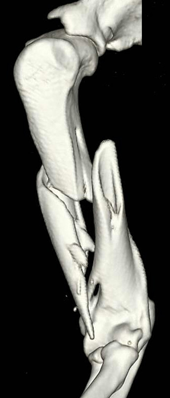
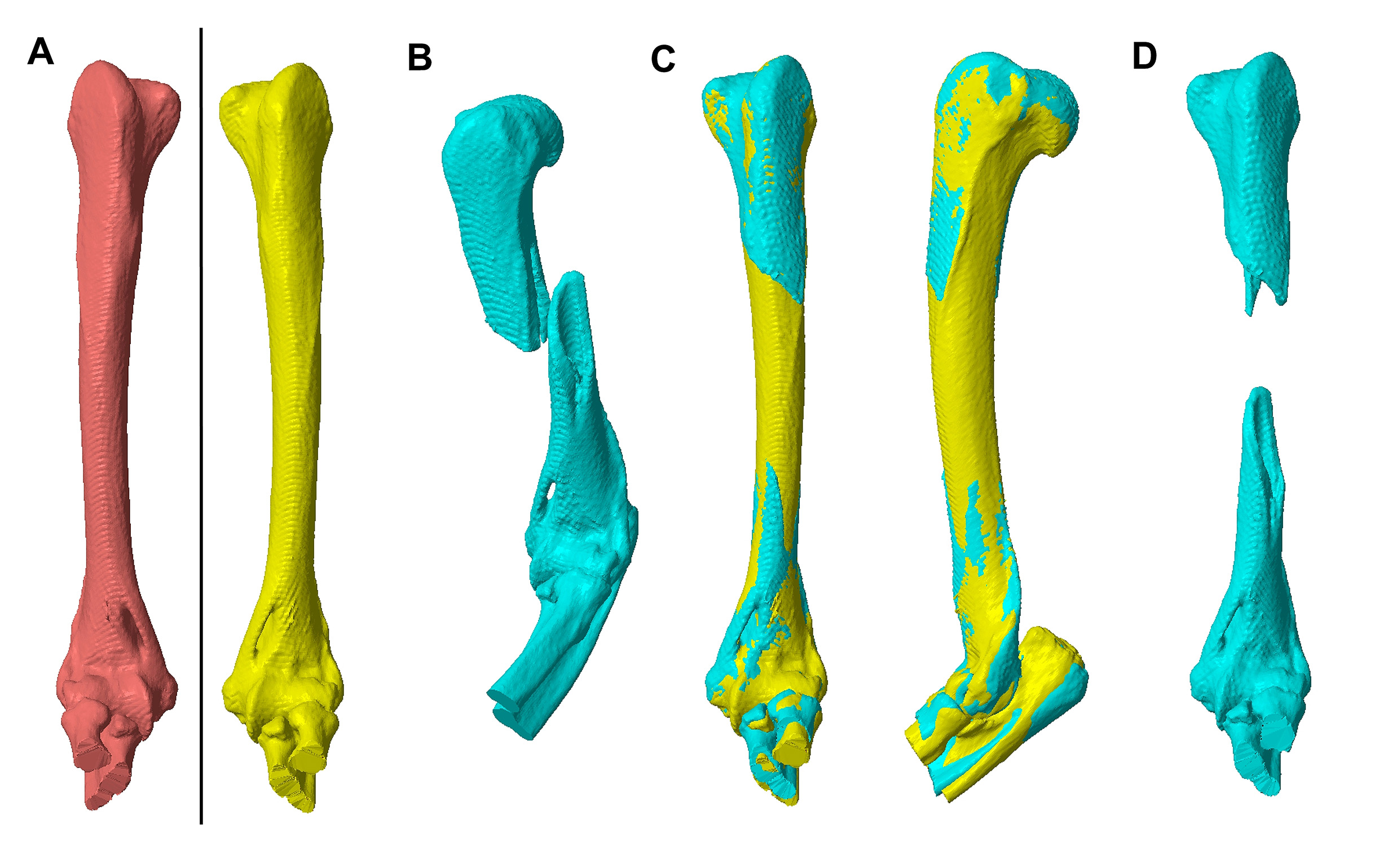
CT data is processed to obtain 3D representations of the fractured bone (Figure 1) and the normal, contralateral bone. These are imported into CAD software, and virtual 3D models of the fracture bone, and the normal contralateral bone, created. These can be manipulated in any plane, allowing the mirrored bone to act as a template for virtual reduction of the major fracture fragments (Figure 2).
Fig 1 – Surface rendered image of the left humerus of a 4.4kg nine year old male neutered Domestic short hair cat showing a comminuted, mid-diaphyseal fracture.
Fig 2 – CAD software images. A virtual representation of the right humerus (in red) is mirrored (in yellow) (A). The major proximal and distal fragments of the left humerus (in blue; B) are orientated in all planes to match to mirrored right humerus (C). Appropriate spatial orientation of the major fracture fragments results (D).
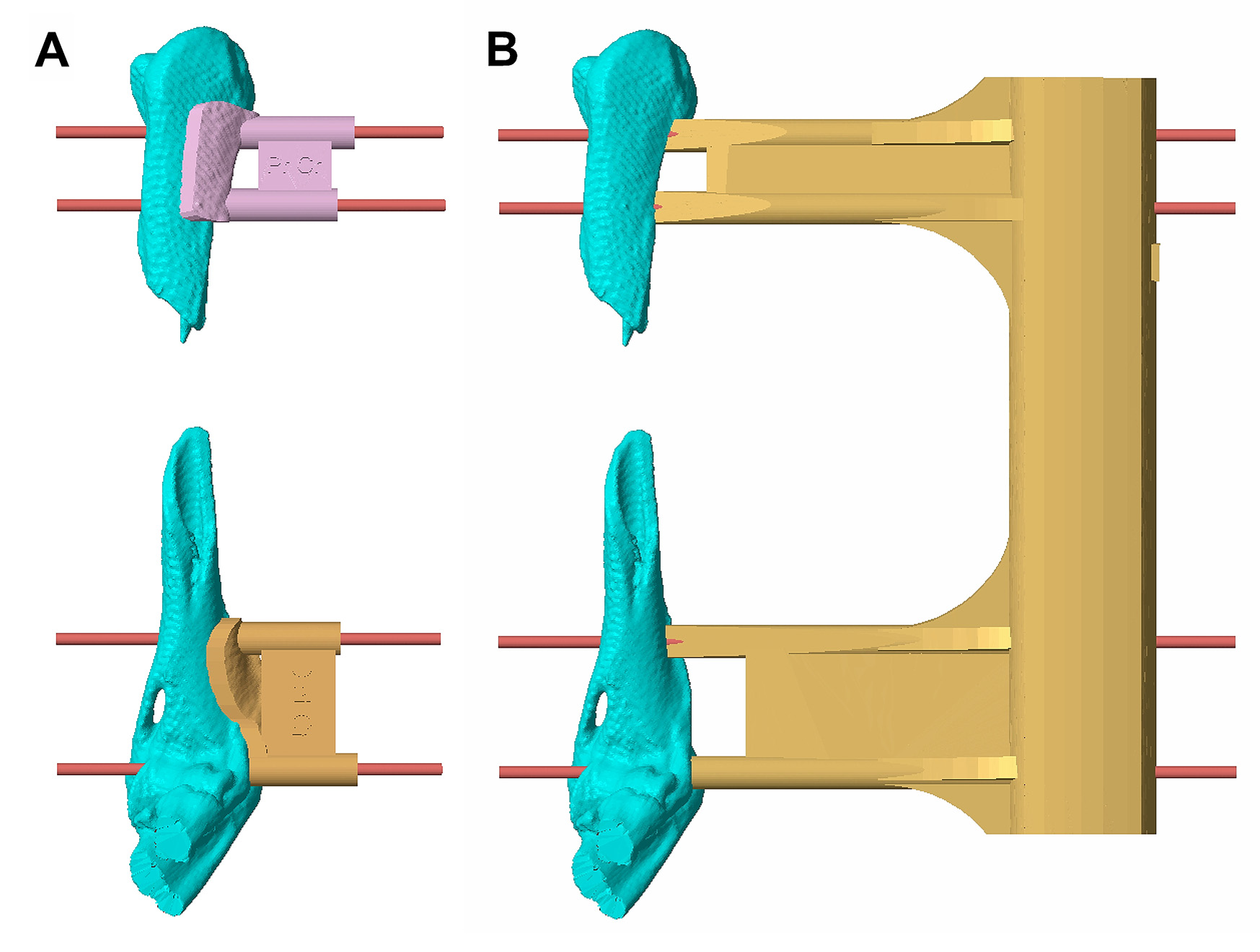
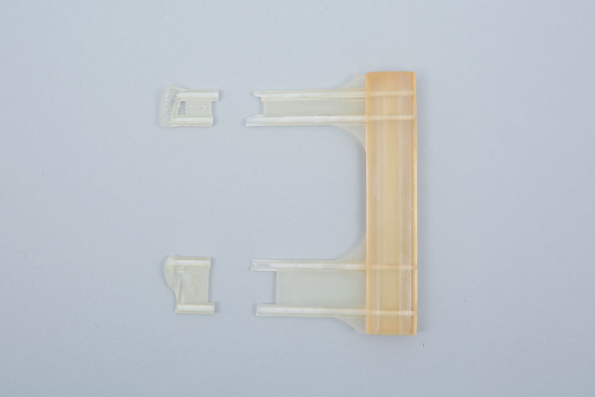
Four parallel virtual Ellis pin trajectories are created, two intersecting the proximal fracture fragment and two the distal fragment; this are positioned to leave space for subsequent plate application. For each bone fragment a virtual Ellis pin orientation guide is created; key features include a contact surface comprising an inverted virtual representation of a segment of cortex (such that the finished guide fits onto the cortex in a unique position) and two Ellis pin channels (Figure 3). Subsequently a virtual reduction guide is created; when applied over the Ellis pins, the planned orientation of the major fracture fragments results (Figure 3). These guides, as well as the major fracture fragments and the mirrored contralateral bone, are 3D-printed. The mirrored bone print allows a plate to be pre-contoured, reducing the requirement for this to be repeatedly passed through an epiperiosteal channel during surgery (Figure 4). Ellis pin orientation guides are applied via standard MIPO portals, the guides removed, and the reduction guide applied over the Ellis pins (Figure 5). The precontoured plate is then applied adjacent to the reduction guide footprints and through an epiperiosteal tunnel. Figures 6 and 7 show post-op radiographs and CAD alignment comparison. Fracture healing progressed uneventfully (Figure 8) and functional outcome was excellent.
Fig 3 – Four parallel virtual Ellis pin trajectories are superimposed on the orientated major fracture fragments. The two virtual Ellis pin orientation guides include contact surfaces comprising an inverted virtual representation of a segment of cortex, and two channels corresponding to the Ellis pin trajectories (A). The virtual reduction guide will align the fracture fragments into the planned relative orientation when slid along the Ellis pins (B).
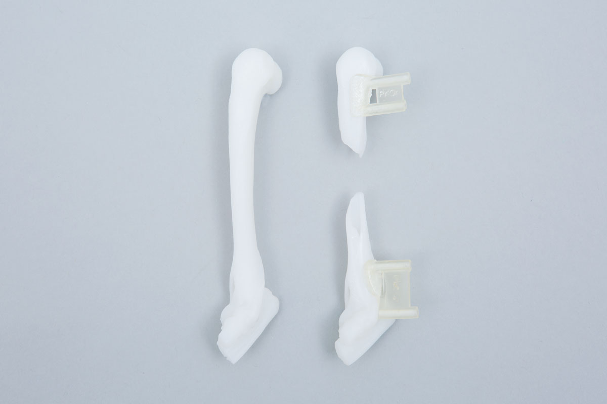
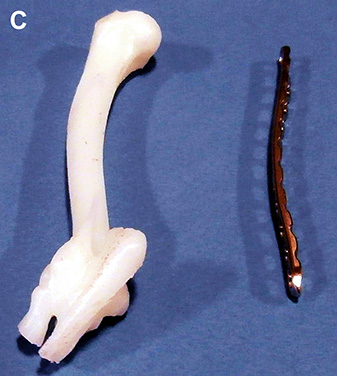
Fig 4 – The two 3D printed Ellis pin orientation guides and the reduction guide (A). The Ellis pin orientation guides in their respective positions on 3D printed major proximal and distal fracture fragments (B). The 3D printed mirrored contralateral humerus with a pre-contoured 2.4mm LCP (C).
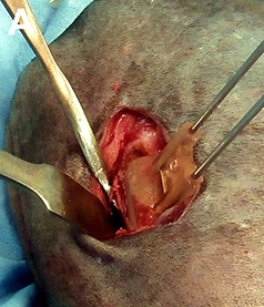
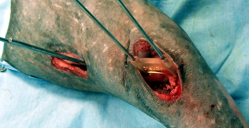
Fig 5 – The proximal Ellis pin orientation guide has been positioned and both pins placed (A). The distal orientation guide and pins in-situ (B); the proximal guide has been removed. The distal orientation guide has also been removed, and the reduction guide slid along the Ellis pins aligning the major fragments to the planned relative orientations (C).
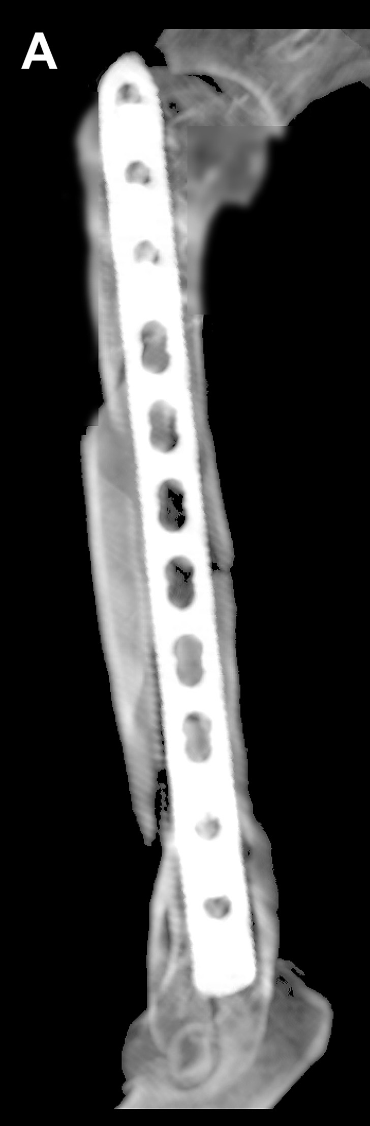
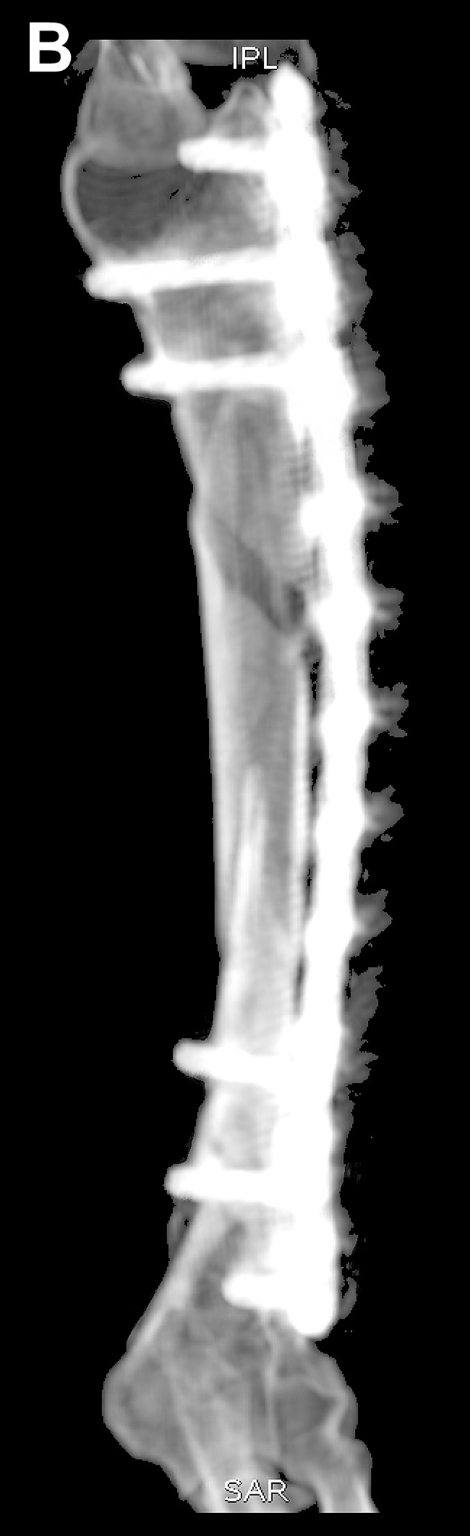
Fig 6 – Post-operative maximal intensity projection CT images.
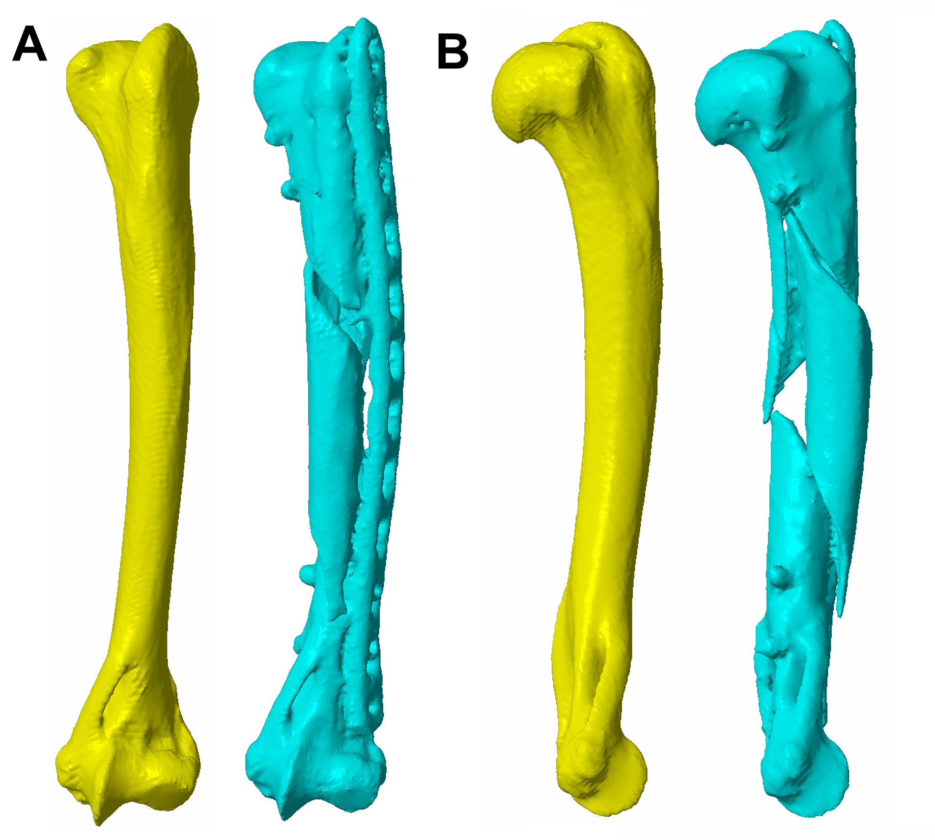
Fig 7 – CAD images showing comparison of post-operative (blue) and mirrored contralateral (yellow) humeral conformation.
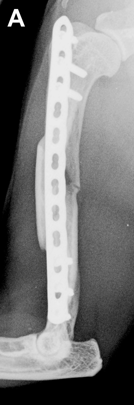
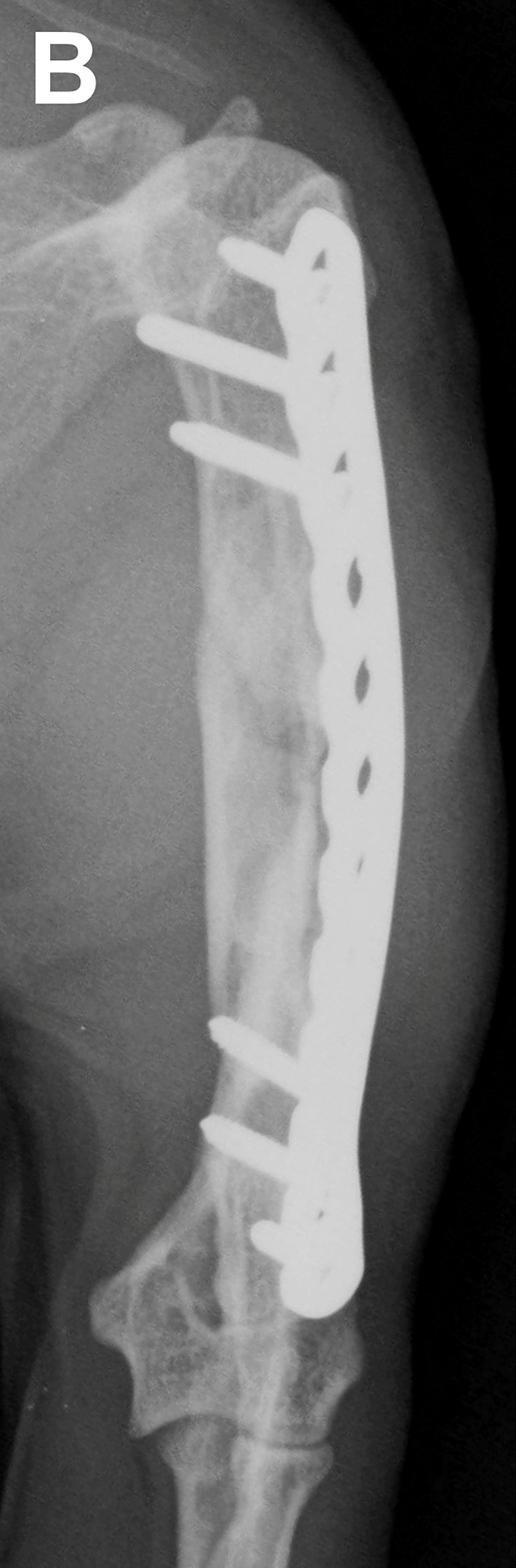
Fig 8 – Four month follow-up radiographs showing almost complete bridging of the fracture site with mineralised callus.
3D printing
For most cases the following models and guides are printed –
- Major fracture fragments - to practice Ellis pin orientation guide fit (usually in autoclavable resin)
- Mirrored contralateral bone – for plate precontouring (usually in non-autoclavable resin)
- Ellis pin orientation guides and reduction guides (autoclavable and biocompatible resin)
Please see Price Guide for additional information
Open Reduction and internal fixation
Virtual surgical planning and guide design
Even when open fracture reduction is planned, achieving optimal orientation of the major proximal and distal fragments can be challenging when comminution precludes reconstruction. These difficulties can be compounded in small patients, and when key fragments are small.
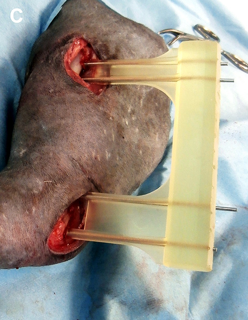
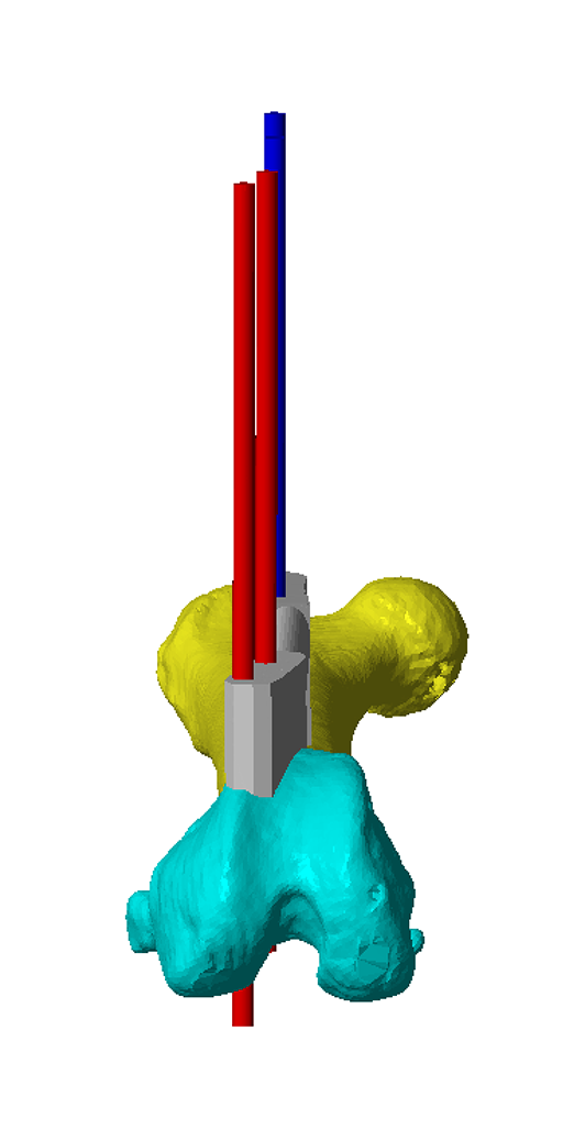
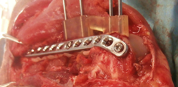
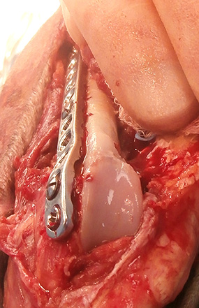
The principles and process of guide design are very similar to those described in detail for guided MIPO reduction. Ellis pin orientation guides are however typically positioned closer to the fracture, and the reduction guide is shorter and can run directly between the pin pairs (Figure 9). A 2.4mm LCP has been applied lateral to the reduction guide (Figure 10); the guide and pins were then removed and a second cranial plate applied.
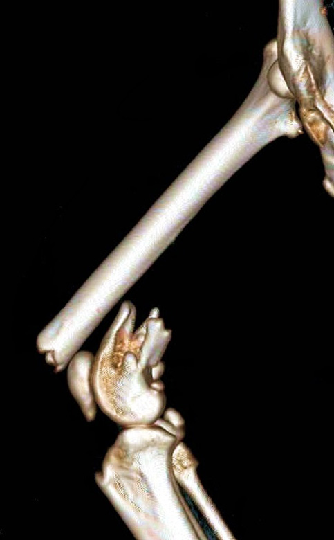
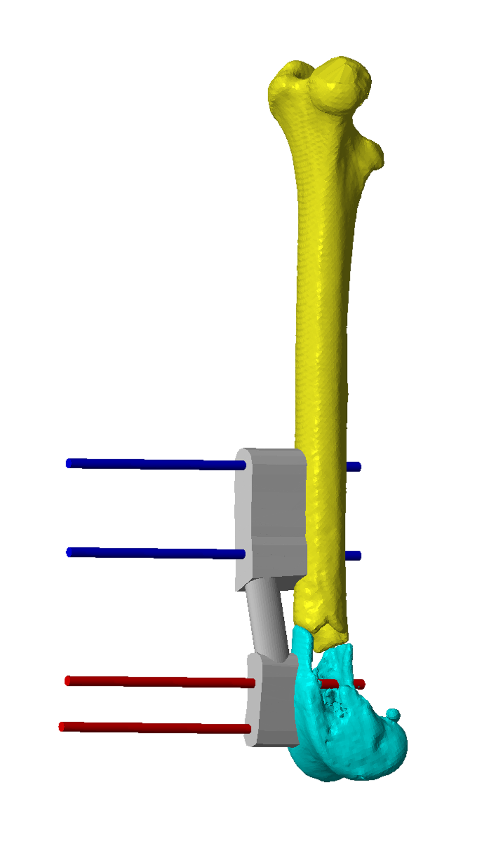
Fig 9 – A comminuted distal metaphyseal femoral fracture in a 4.7kg nine year old male Domestic short hair cat which was referred after an aborted attempt at surgical stabilisation. There are two small comminuted fragments and very limited distal bone stock (A). The major fracture fragments have been orientated via shape matching to the mirrored, contralateral femur, and Ellis pin orientation guides and a reduction guide created (B and C).
Fig 10 - A 2.4mm LCP has been applied lateral to the reduction guide.
3D printing
For most cases the following models and guides are printed –
- Major fracture fragments - to practice Ellis pin orientation guide fit (usually in autoclavable resin)
- Mirrored contralateral bone – for plate precontouring (usually in non-autoclavable resin)
- Ellis pin orientation guides and reduction guides (autoclavable and biocompatible resin)
Please see Price Guide for additional information
UK patent application (1703621.1) / Intellectual Property Office Registered Design number 6003208
©Copyright 2017 - Vet 3D | Terms & Conditions | Cookie Policy