- Login
- Sign Up
- Online referral form
This site is optimised for modern web browsers, and does not fully support your version of Internet Explorer, some sections of the website may not work correctly such as web forms


Surgical Rehearsal
Surgery can be practiced on 3D-printed bone models which can be cut, drilled, and have implants applied. Surgical rehearsal can be helpful in many scenarios, but is probably most often used to practice angular limb deformity corrections and less commonly limb sparing surgery.
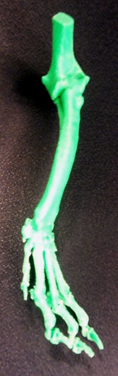
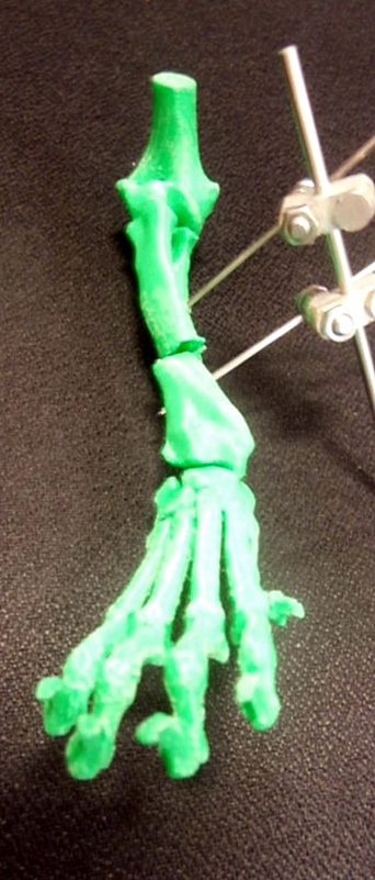
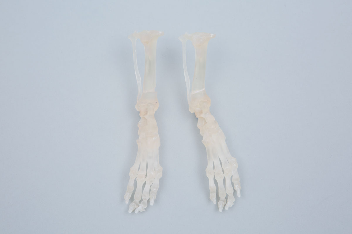
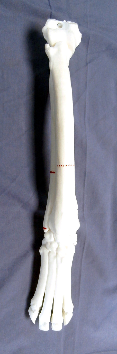
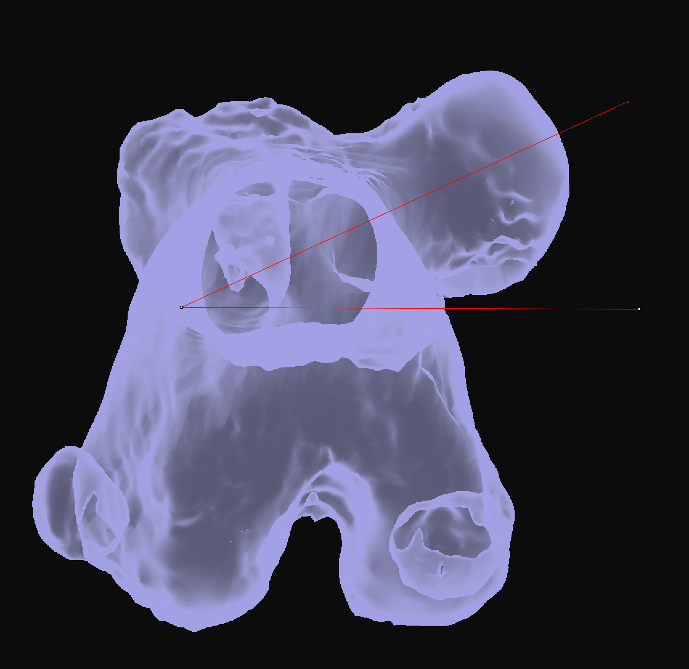
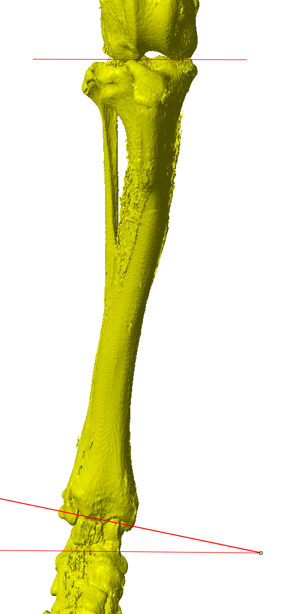
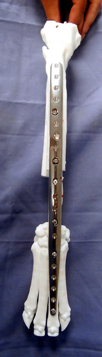
Figure 1 shows a 3D printed antebrachial deformity following osteotomy, realignment, and temporary fixation with an ESF. A plate was then precontoured to the radius in the corrected orientation. This approach is well-suited to an opening wedge approach; key surgical steps include correct osteotomy positioning (which can be judged from landmarks and comparison to the osteotomised bone model) and appropriate alignment of the distal segment (which is significantly facilitated by a pre-contoured plate which acts as an alignment guide). A variation on this approach is to mark the optimal osteotomy position on the 3D-printed bone. Figure 2 shows a 3D-printed crus from a Dachshund with pes varus. The osteotomy site was carefully positioned on the 3D bone model in the CAD to leave space for two plate screws in the distal fragment. A position and plane of the osteotomy can be indicated in the 3D-printed bone to act as guide in theatre. In this case a post-opening wedge bone model was also printed to permit pre-contouring of the plate.
Figure 1 – A 3D-printed antebrachial deformity (A). A mid-radial osteotomy has been made, the distal segment realigned, and a temporary external fixator applied (B) to maintain the planned orientation whilst a plate is pre-contoured.
Figure 2 – 3D printed bones from a Dachshund with pes varus. The optimal position and plane of the distal tibial osteotomy were identified on the 3D bone model within the CAD software. These were marked so as to be visible when 3D-printed. A post-opening wedge bone model was also printed to permit pre-contouring of the plate.
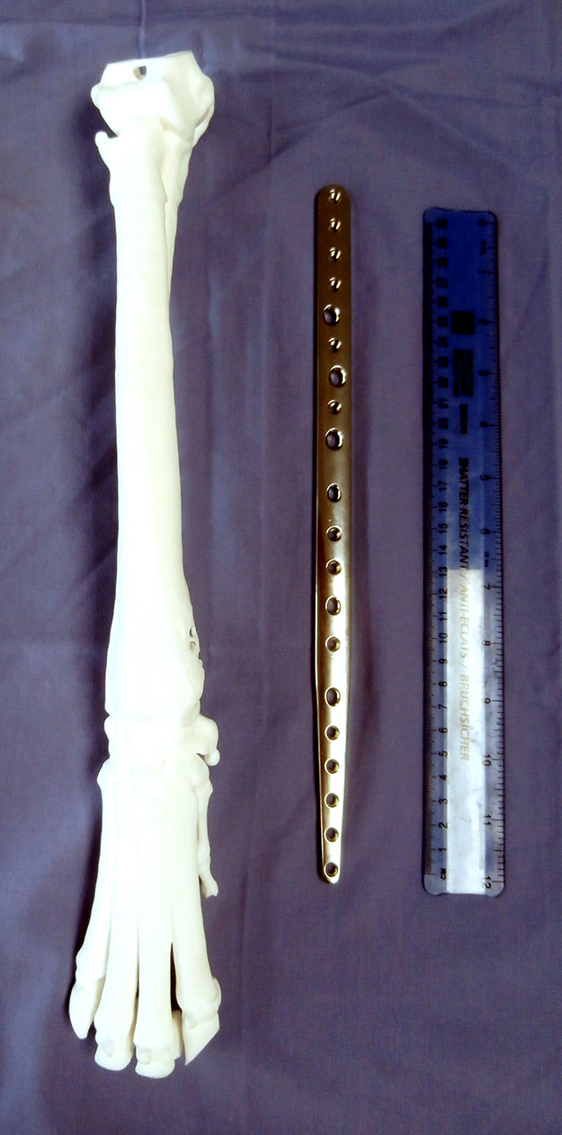
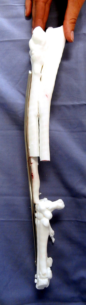
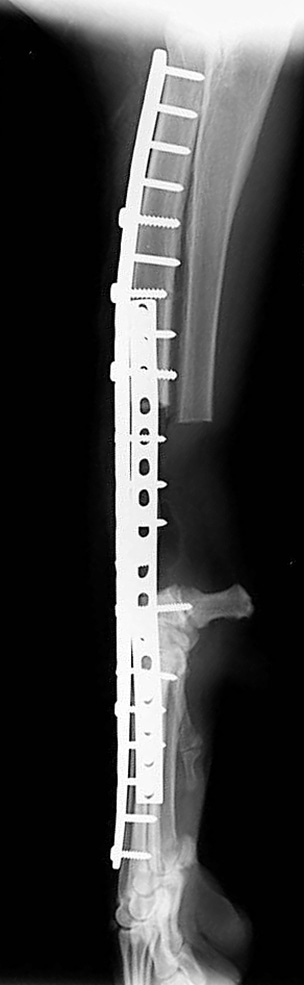
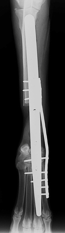
Figure 3 shows a series of surgical rehearsal steps for an ulnar roll-in limb spare procedure for treatment of a distal radial osteosarcoma in an eight year old Great Dane. Planned radial and ulnar osteotomies were practised, ensuring appropriate subsequent limb alignment and length with respect to the pre-operative conformation and the custom plate to be applied. Additionally this plate was pre-contoured to conform to the original relative orientations of the proximal radius and third metacarpal; this significantly assisted restoration of appropriate limb alignment following resection of the distal radius and ulnar transposition.
Figure 3 – A 3D-printed antebrachium from an eight year old Great Dane with distal radial osteosarcoma, and a custom limb-spare plate (A). The extent of distal radial resection (90mm) is planned based on CT assessment of the extent of the neoplasm (B). An ulnar roll-in procedure was planned, osteotomies made, and the positions of screw holes in the transposed segment assessed (C and D). The plate was pre-contoured to conform to the original relative orientations of the proximal radius and third metacarpal and applied to the bone, including fixation of the ulnar segment (E and F). This significantly assisted restoration of appropriate limb alignment following resection of the distal radius and ulnar transposition; post-operative radiographs showed appropriate limb alignment and implant positions (G and H). Gait at two days following surgery (I - below).
Please note that in general the process whereby a 3D representation of a bone is created from DICOM data (termed segmentation) requires that a threshold Hounsfield unit be set defining which voxels are kept and which discarded. Thus mature cortical bone is easily differentiated from soft tissue, resulting in very accurate segmentation of both the periosteal and endosteal cortical surfaces. Trabecular bone, and very soft immature cortical bone, are less easily segmented, thus similarly accurate reproduction of internal trabecular bone detail in a 3D-printed bone should not be relied upon. It should also be noted that all internal structures are sometimes removed during CAD processing for various reasons (usually as part of more complex CAD procedures - however please specify if you require these to be maintained).
©Copyright 2017 - Vet 3D | Terms & Conditions | Cookie Policy