- Login
- Sign Up
- Online referral form
This site is optimised for modern web browsers, and does not fully support your version of Internet Explorer, some sections of the website may not work correctly such as web forms


SOP - Distal Femoral Osteotomy
Pre-operative
- Unless specified otherwise, two bone models and two guides will be supplied.
- Pre-operative femur – translucent yellow plastic – for pre-op / intra-op practice of osteotomy guide fit – this can be autoclaved.
- Post-operative femur – white plastic – usually with footprint of reduction guide in-situ – for pre-contouring of plate – autoclaving not recommended.
- Osteotomy and reduction guides – biocompatible and autoclavable translucent orange plastic. Recommend autoclave protocols are below, however all standard protocols are acceptable.
- 138°C for 3 minutes
- 134°C for 6 minutes
- 121°C for 15 minutes
- Four Ellis pins will be required, and ideally four drill bits of the same or slightly smaller diameter.
- The diameter varies according to patient size and will be confirmed following guide design and in this SOP when supplied with the models.
- The 3D bone models, and especially the osteotomy and reduction guides, are UV light sensitive and should be stored away from direct sunlight (e.g. in a draw or box). Extended exposure to UV light may reduce the strength of the guides.
Intra-operative
- A standard craniolateral approach to the distal femur and stifle is made.
- The osteotomy guide will be applied craniolaterally. The necessary surgical exposure is very similar to that required for non-guided distal femoral osteotomy – the trochlear ridges, and the cranial and lateral aspects of the distal femur. The osteotomy guide footprint extends onto the lateral surface of the femur to a similar extent to that required for plate placement.
- Elevate soft tissues to the extent required for the osteotomy guide footprint.
- Supra-periosteal exposure is appropriate i.e. as for plate application.
- Note that adherent soft tissues of any significant thickness will adversely affect guide fit and should be removed – limited dissection of the proximal attachment of the joint capsule may be necessary.
- Identify the position of osteotomy guide fit.
- This is usually obvious as the guide footprint engages the proximal aspects of the trochlear ridges beneath.
- Comparison to the printed bone helps identify the correct position.
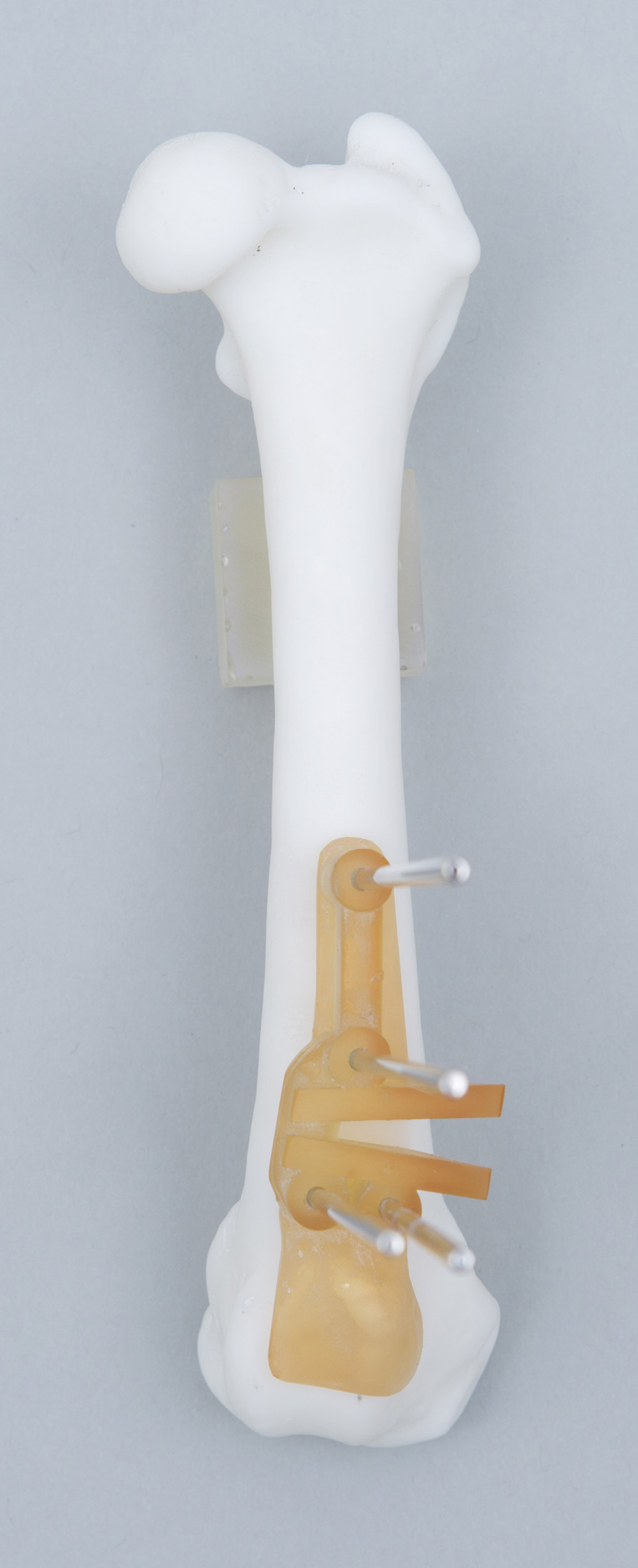
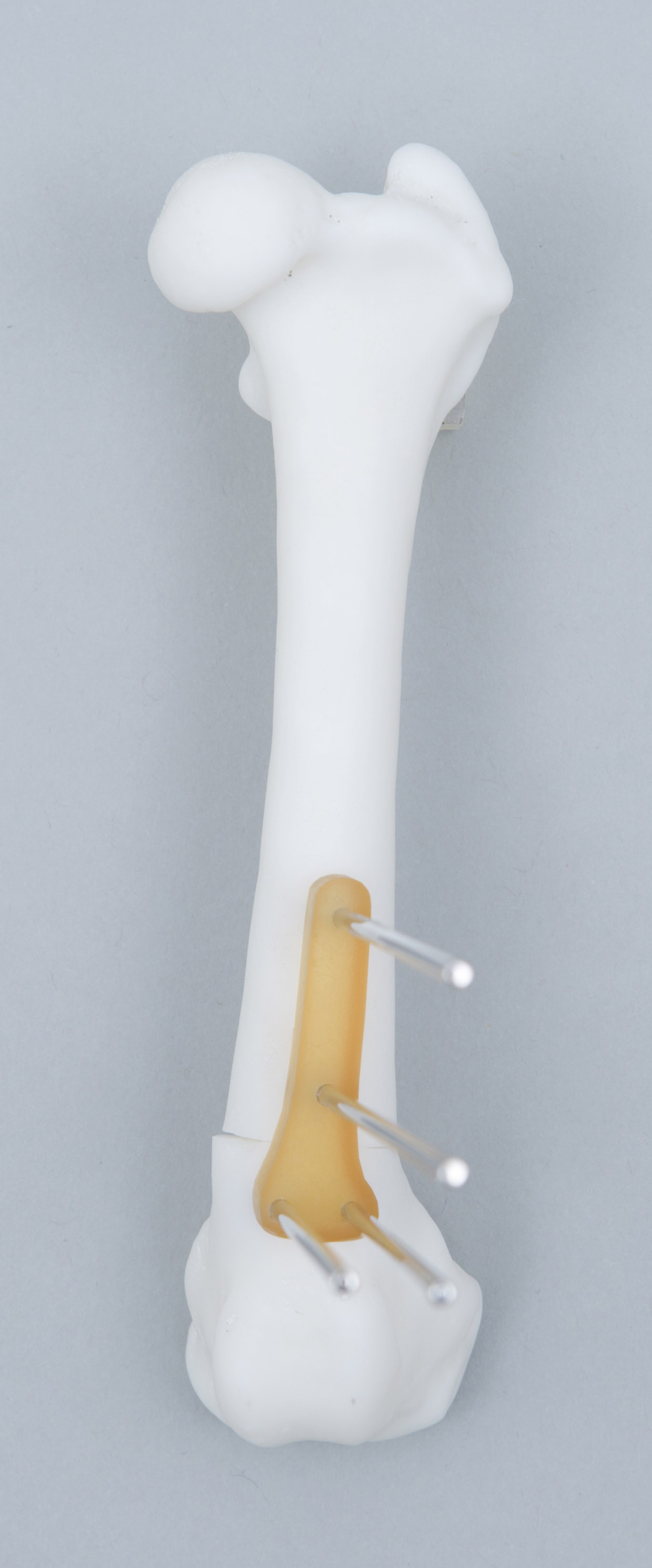
- Apply the Ellis pins through their channels (Figure 1).
- Pre-drilling of the cis-cortex only with a drill bit of the same or slightly smaller diameter than the Ellis pin is recommended. Carefully align the drill bit with any one of the channels such that off-axis pressure on the guide channel (which could move the guide) is avoided. The transparent, cylindrical nature of the channels facilitates alignment.
- Ideally after each cis-cortex is drilled the drill bit is left in-situ and a new bit used for the next hole. In this way the position of the guide cannot change, however with careful technique this can be achieved with fewer drill bits.
- Each drill bit is removed sequentially and replaced with a bicortical Elis pin.
- If the drill chuck, or later the saw attachment, will contact the end of the previously placed pin, that pin can be cut leaving around 1cm emerging from the guide channel.
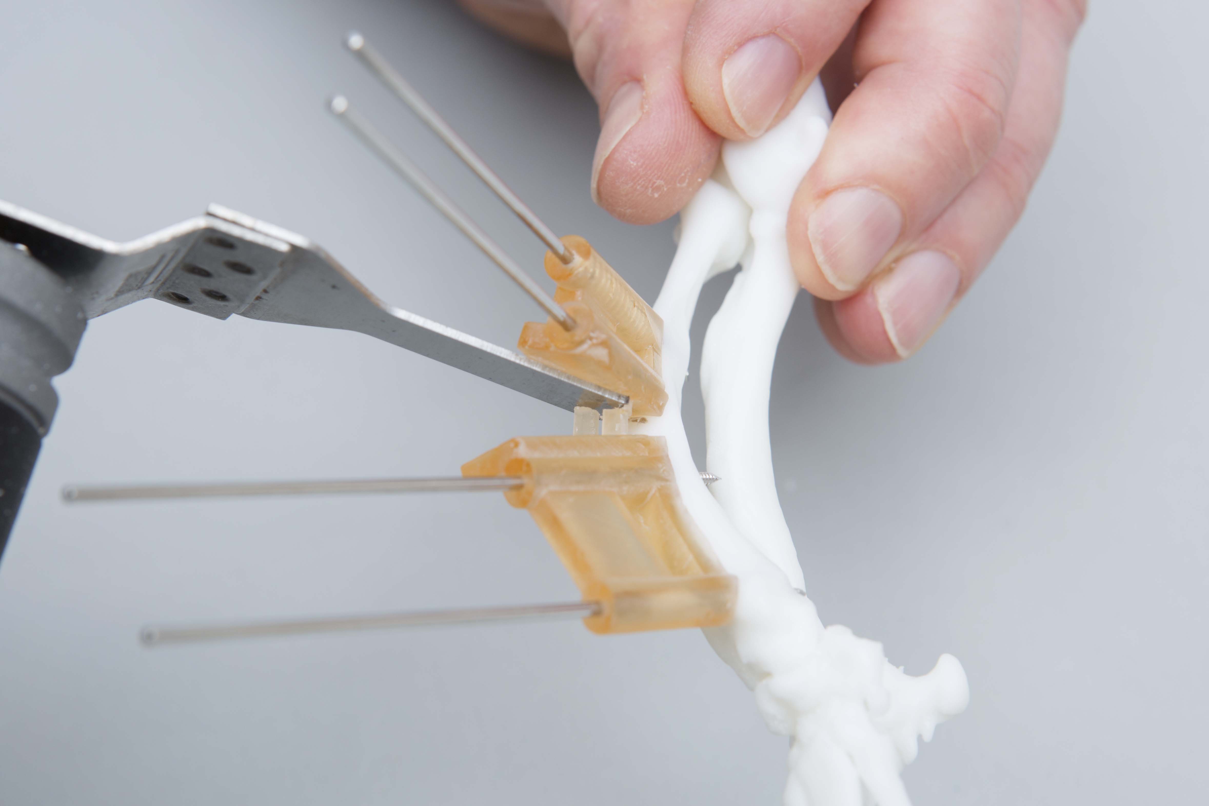
- Cut the connecting bars between the osteotomy guide planes (Figure 2).
- Cut the connecting bars flush with the osteotomy guide plane surfaces using an oscillating saw blade held parallel to, and in contact with, each plane.
- Although the guide material is biocompatible, a moist swab can be placed between the bars and the bone to catch debris, and the area then lavaged.
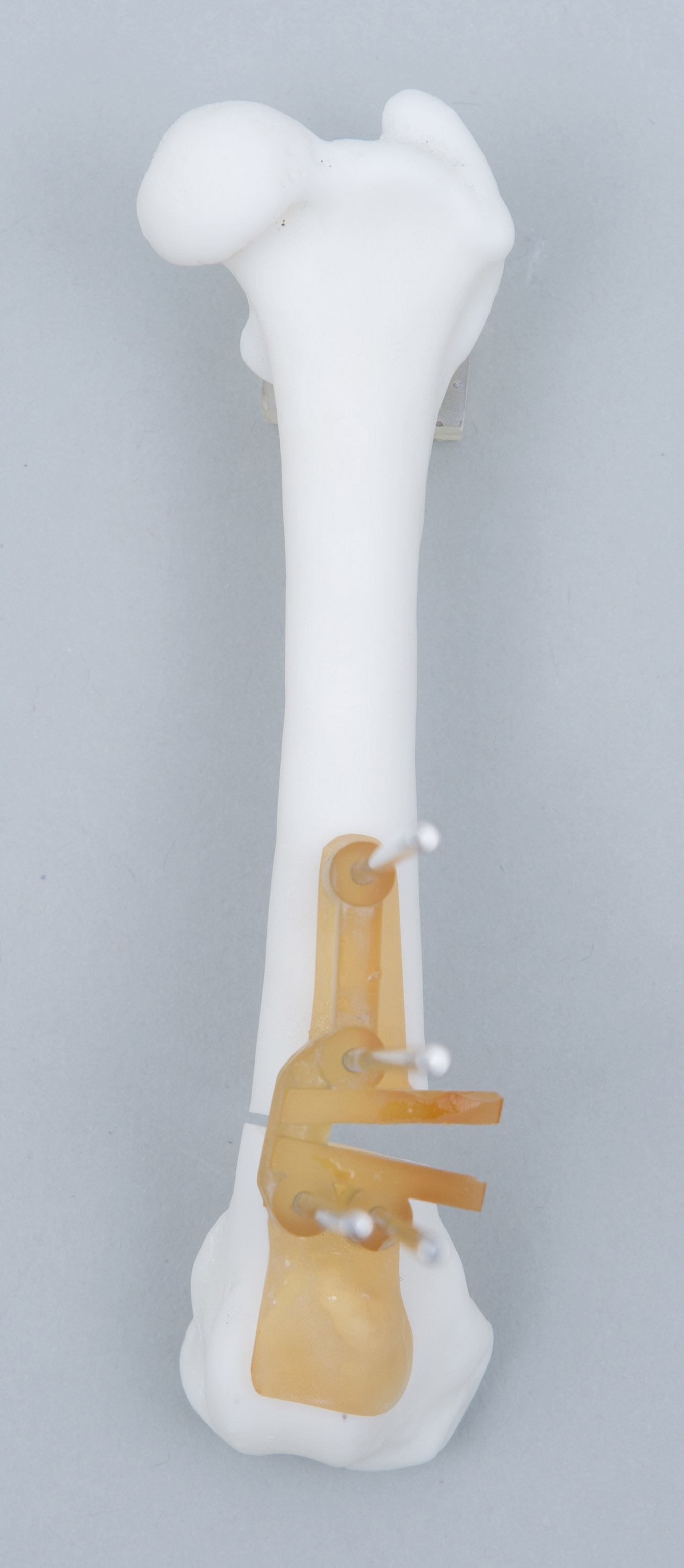
- Make the osteotomy / osteotomies (Figure 3).
- Ensure the oscillating saw blade remains parallel to, and in contact with, each plane.
- Occasionally the guide may ride up the Ellis pins due to contact with the blade – a bone clamp or manual pressure will prevent this.
- It is often helpful to change the angle of attack of the blade once the osteotomy has been started. This is sometimes necessary to avoid contact between the saw and the top of the guide plane.
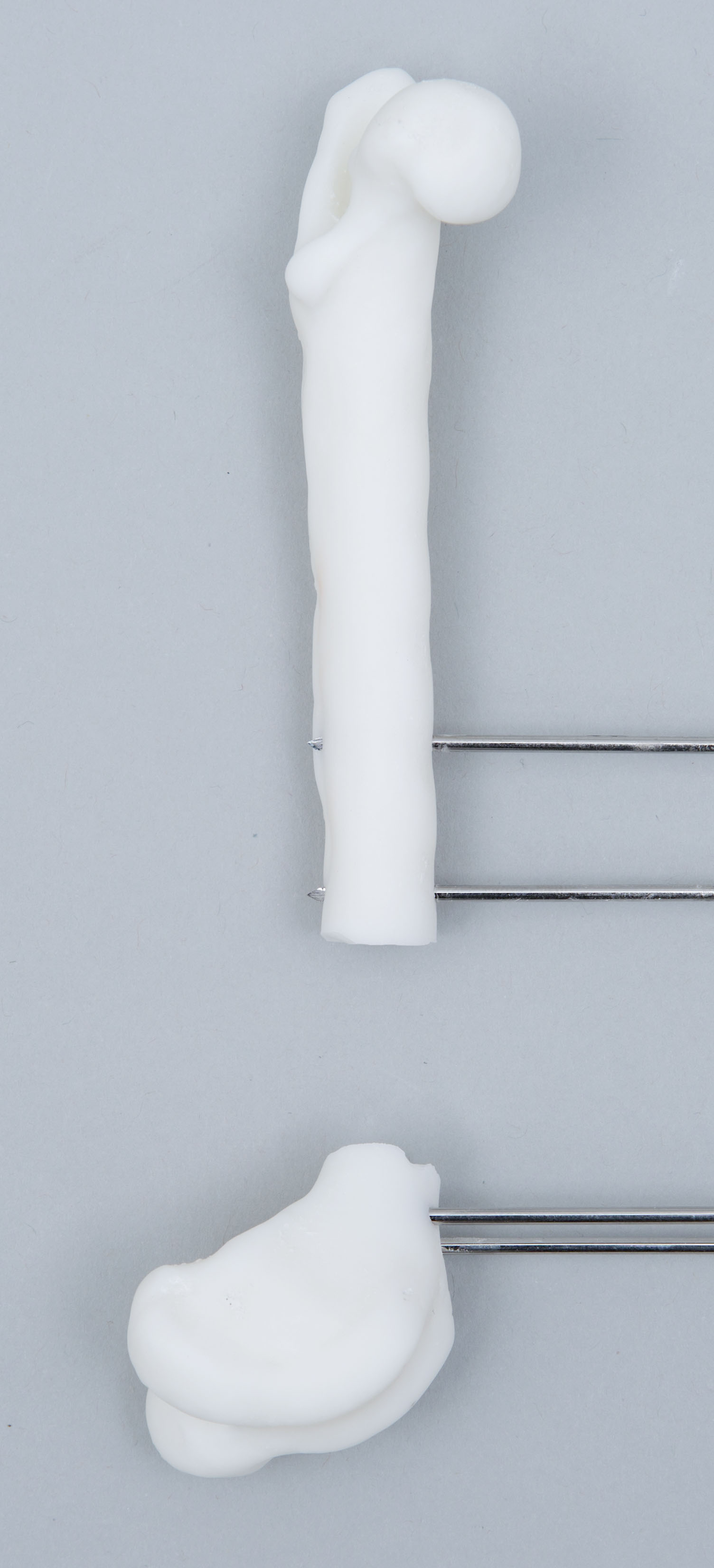
- Remove both ends of the osteotomy guide (Figure 4).
- These should slide off the Ellis pins.
- Place the reduction guide (Figure 5).
- This will align all four Ellis pins in parallel, and, when contacting the cortex proximally and distally, results in optimal re-orientation of the proximal and distal bone segments as pre-planned.
- Note that for closing wedge osteotomies the guide may bind due to friction between the osteotomy surfaces if these are poorly aligned. It is very helpful to manually reduce the bone segments with all four Ellis pins parallel and the osteotomy surfaces appropriately reduced before sliding the reduction guide down the Ellis pins.
- Full length Ellis pins are not necessary – it is easier to slide the guide if these have been shortened. Sterile lubricating jelly applied to the pins can also make it easier to place the guide.
- Contact between the guide base and the cortex proximally and distally is necessary for planned alignment – if required non-pointed reduction forceps can be used to push the guide onto the bone.
- Please note the reduction guide is designed to be as strong as possible within the size limitations imposed by patient size, but is not indestructible. Avoid the use of excessive force or application of point loading (e.g. pointed reduction forceps) – large forces should not be necessary if the above guidelines are followed.
- Apply the precontoured plate (Figure 6).
- This will be applied laterally, adjacent to the reduction guide.
- Check that the Ellis pins do not impede planned screw pilot holes. Should this occur pilot holes for cortical screws can usually be slightly angled; for locking screws removal of the Ellis pin once sufficient other screws have been placed is necessary.
- Do not attempt to compress the osteotomy with the reduction guide attached with all four Ellis pins as this will produce stress at the pin / bone interface. If you wish to compress the osteotomy the plate should be applied securely with at least two screws either proximally or distally. A screw is placed at the other end of the plate in a loaded position, in contact with the plate but not tightened. One pair of Ellis pins is removed (from either end), and the screw tightened. Obviously undesired relative movement of the osteotomy segments is possible but unusual unless plate contouring is inaccurate. Lightly applied bone-holding forceps between the reduction guide and bone can help maintain alignment but still permit slight compressive movement of the bones.
- Remove the reduction guide and Ellis pins.
Post-operative
- We actively encourage feedback – please let us know your thoughts.
Figure 1 – The osteotomy guide has been applied to the cranial surface of the femur and stabilised with four Ellis pins
Figure 2 - Oscillating saw plane orientation (parallel to and in contact with the osteotomy guide plane) during connecting bar cutting and the osteotomy
Figure 3 – the osteotomies have been completed parallel to the guide planes
Figure 4 – the two ends of the osteotomy guide have been removed
Figure 5 – the reduction guide has been slid along the Ellis pins aligning the proximal and distal bone segments as planned. Reduction is maintained for plate placement
Figure 6 – the precontoured plate is applied adjacent to the reduction guide. The guide and pins are then removed
Download as PDF -
![]()
Distal
Femoral
Osteotomy
©Copyright 2017 - Vet 3D | Terms & Conditions | Cookie Policy