- Login
- Sign Up
- Online referral form
This site is optimised for modern web browsers, and does not fully support your version of Internet Explorer, some sections of the website may not work correctly such as web forms


Spinal stabilisation – vertebral pedicle screws
Stabilisation of two (or more) vertebrae may be considered for treatment of a number of conditions including atlantoaxial subluxation, caudal cervical spondylomyelopathy, vertebral deformitiesd, degenerative lumbosacral stenosis, discospondylitis, and fractures.
Traditional methods of fixation have included intervertebral spacers (e.g. cement plugs, tantalum blocks) and vertebral plating or screw / polymethylmethacrylate constructs, often in combination with an attempt to promote osseous fusion between the vertebrae. Unfortunately the relative weakness of vertebral bone, and the inability to place bicortical screws, has led to relatively high rates of endplate collapse, implant migration and screw loosening. Locking constructs reduced the rate of screw loosening but at the expense of screw cut-through and pull-out. It remains unclear whether cage intervertebral spacers or disc replacement will represent a solution to these challenges.
Patient-specific drill guides permit placement of multiple pedicle screws in a single vertebrae, significantly increasing screw working length and permitting bicortical placement. The potential to use locking screws (with a high core diameter) in a locked construct further increases the strength of the overall osteosynthesis, and renders conventional failure modes improbable.
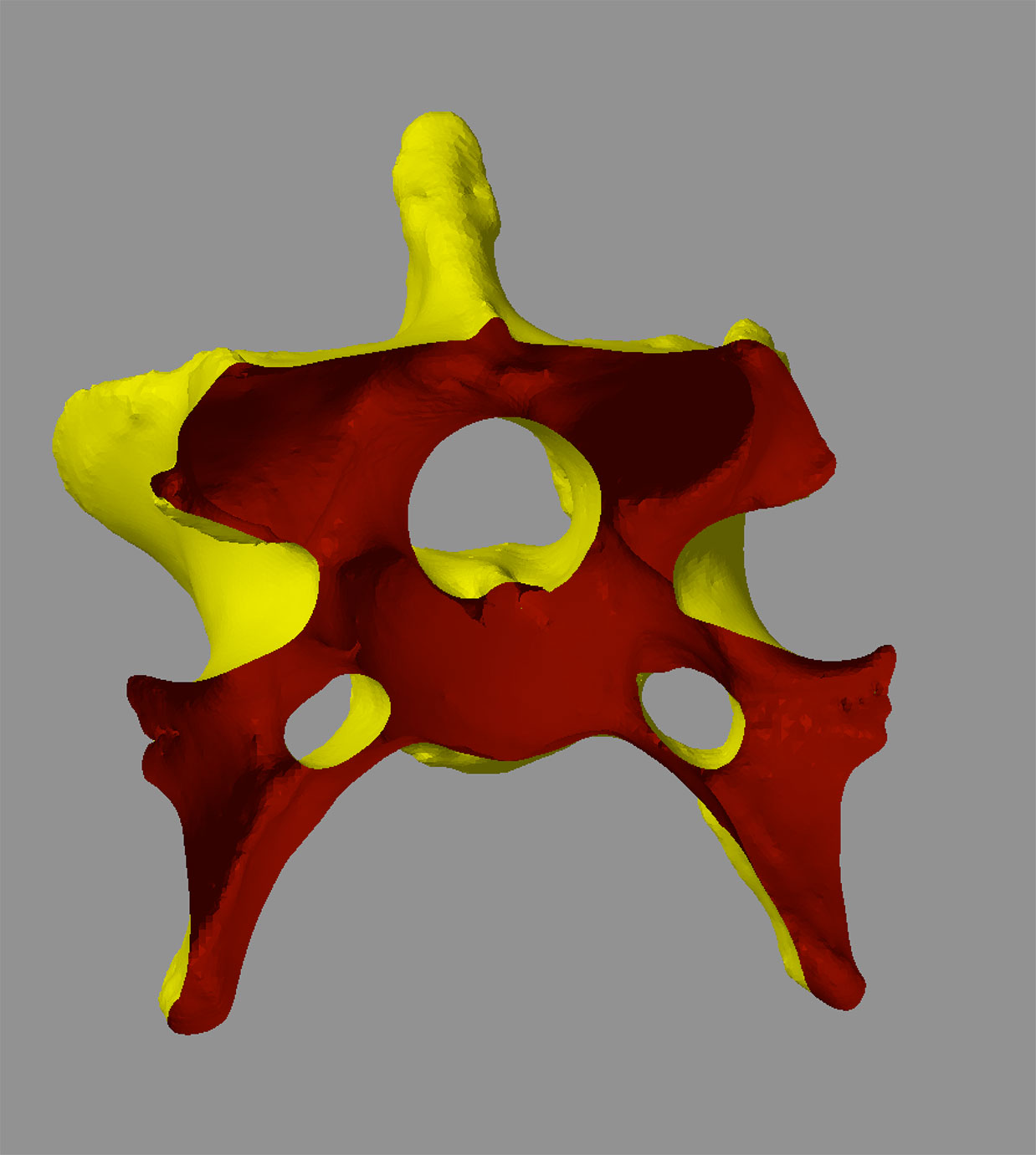
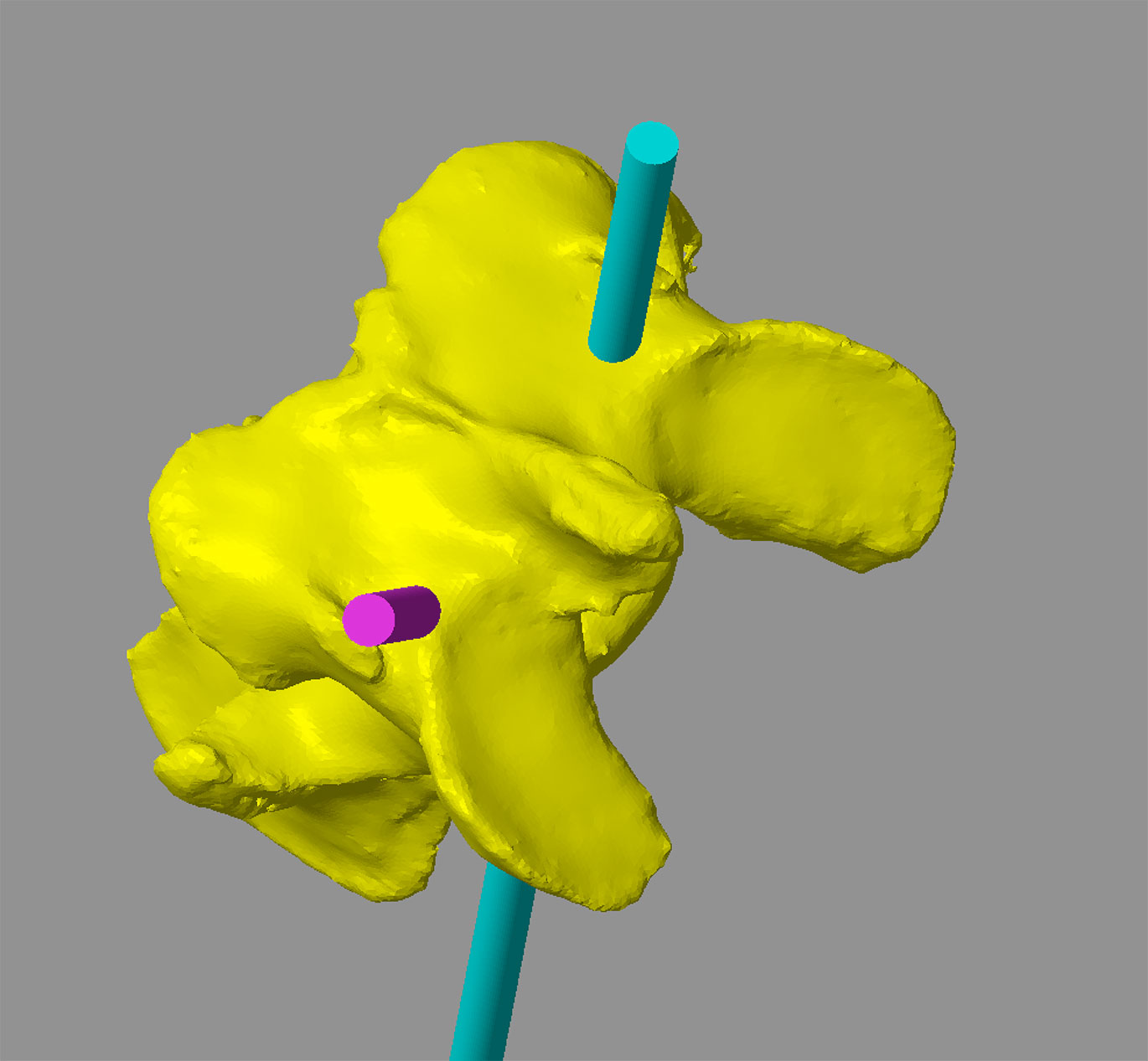
Guides are designed based on CT data which are used to create a virtual 3D representation of the vertebra in CAD software which can be viewed from any angle or in cross-section (Figure 1). A cylinder with the same diameter as the planned screw is created, representing its virtual trajectory through the vertebra (Figure 2). This trajectory can be adjusted in six degrees of freedom until optimised. Key criteria include –
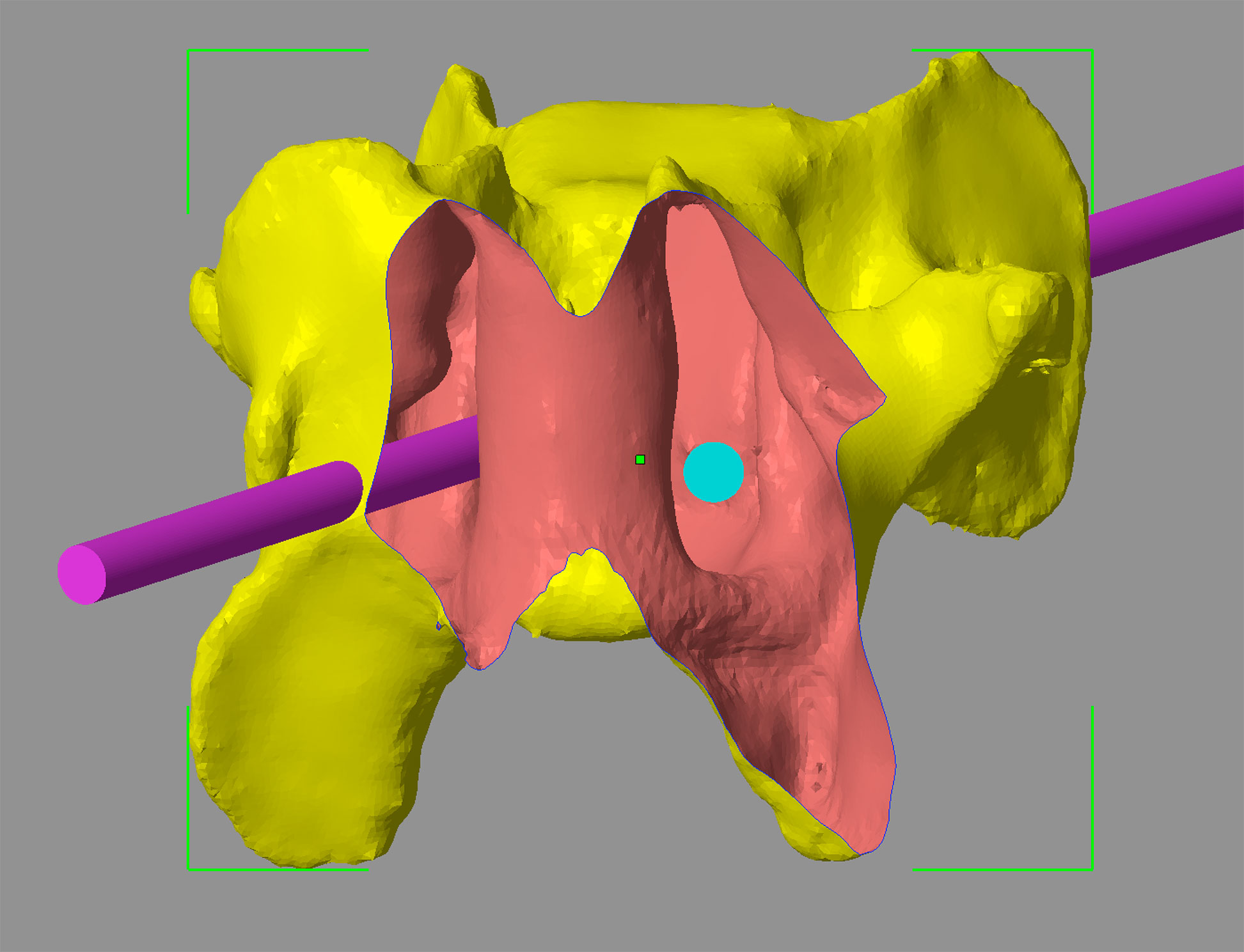
• Appropriate entry and exit points maximising bone stock and avoiding important structures (Figure 3)
• A central position within the pedicle (Figure 4).
• Consideration of drill angle with respect to surgical access (especially relevant for the caudal cervical spine).
Figure 1 – A CAD virtual 3D representation of the sixth cervical vertebrae from a seven year old Dalmatian weighing 36kg with caudal cervical spondylomyelopathy (Case 1) (A). The same vertebra in transverse cross-section permitting visualisation of the vertebral canal and transverse foraminae (B).
Figure 2 – Transverse cross-section of C6 showing virtual 3.5mm diameter trajectories of two of the four planned pedicle screws. The position and orientation of the trajectories can be adjusted with six degrees of freedom until optimal entry and exit points, and relationship to the vertebral canal and transverse foraminae, are achieved.
Figure 3 – Entry points are planned immediately caudal to the C5-C6 disc (A). Exit points are adjusted to avoid the C5-C6 facet joints (B).
Figure 4 – A cross-section of C6 in a plane perpendicular to the long axis of one of the 3.5mm screw trajectories. The abaxial border of the vertebral canal is to the left of the trajectory, and the axial border of the transverse foramen to its right; the planned trajectory of the screw is centrally positioned within the pedicle.
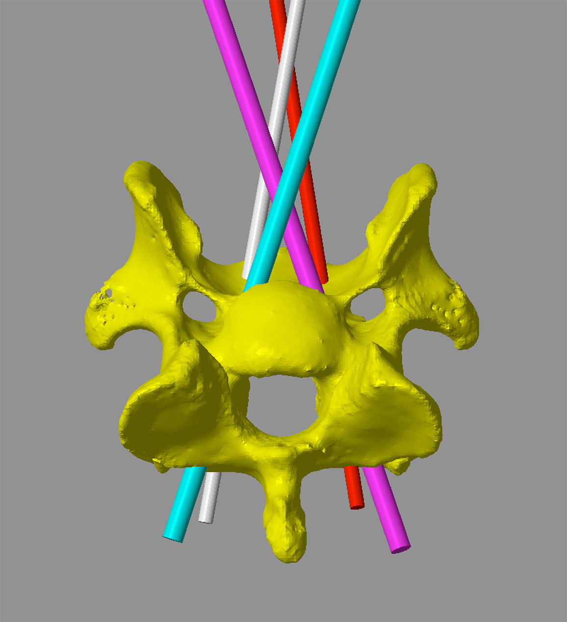
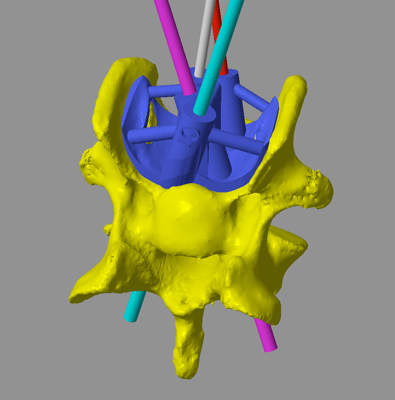
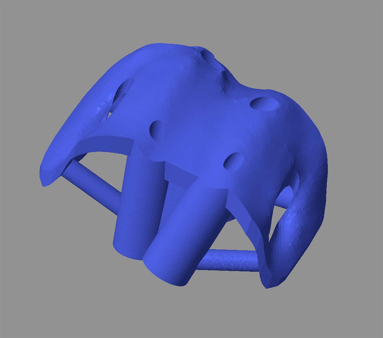
Once finalised, the diameter of each screw trajectory is reduced to the desired pilot hole size (Figure 5), and a drill sleeve created around each trajectory. The second key element of the drill guide is a bone contact surface that precisely reflects the contours of the vertebral cortex. In this way, the finished guide will fit only in a single, unique position, thus appropriately orientating the drill sleeves relative to the vertebra (Figure 6). Guide fit is usually excellent due to the highly contoured nature of the most vertebral cortices. Drill guides are 3D printed in biocompatible, autoclavable plastic (Figure 7).
Figure 5 – The four planned screw trajectories. The more cranial trajectories (blue and pink) are 2.8mm in diameter (pilot hole size for a 3.5mm locking screw). The more caudal trajectories (white and red) are 2mm in diameter (pilot hole size for a 2.7mm locking screw).
Figure 6 – The virtual drill guide in-situ (A) showing drill sleeves for each pilot hole (A). The contact-surface of the guide precisely reflects the contours of the ventral vertebral cortex (B).The cut-away sections are necessary to avoid areas when the axial cortices of the wings overhang the regions more dorsally – these would otherwise prevent placement of the guide.
Figure 7 – A 3D printed model of C6 with the drill guide in-situ.
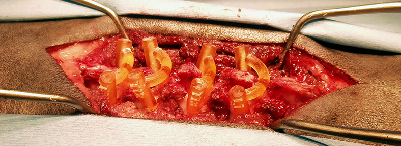
Guides are placed following a standard surgical approach to the appropriate aspect of the vertebrae to be stabilised. Removal of soft tissue from the region of cortex corresponding to the guide footprint is important to optimise guide fit (Figure 8). Once in position each pilot hole is drilled sequentially (Figure 9); it is helpful to leave the first drill bit in place to maintain the position of the guide whilst the other holes are drilled. A 3D-printed model of the vertebrae including screw pilot holes is helpful both for reference regarding guide placement and for screw length measurement. (Figure 10). The screws are then placed; locking screws are preferred over cortical screws (due to their greater core diameter) or threaded pins (due to the better interlock with PMMA). In most cases screws are left long, and the protruding portions bonded with polymethylmethacrylate (Figure 12).
Post-operative CT images are shown in Figures 13-15.
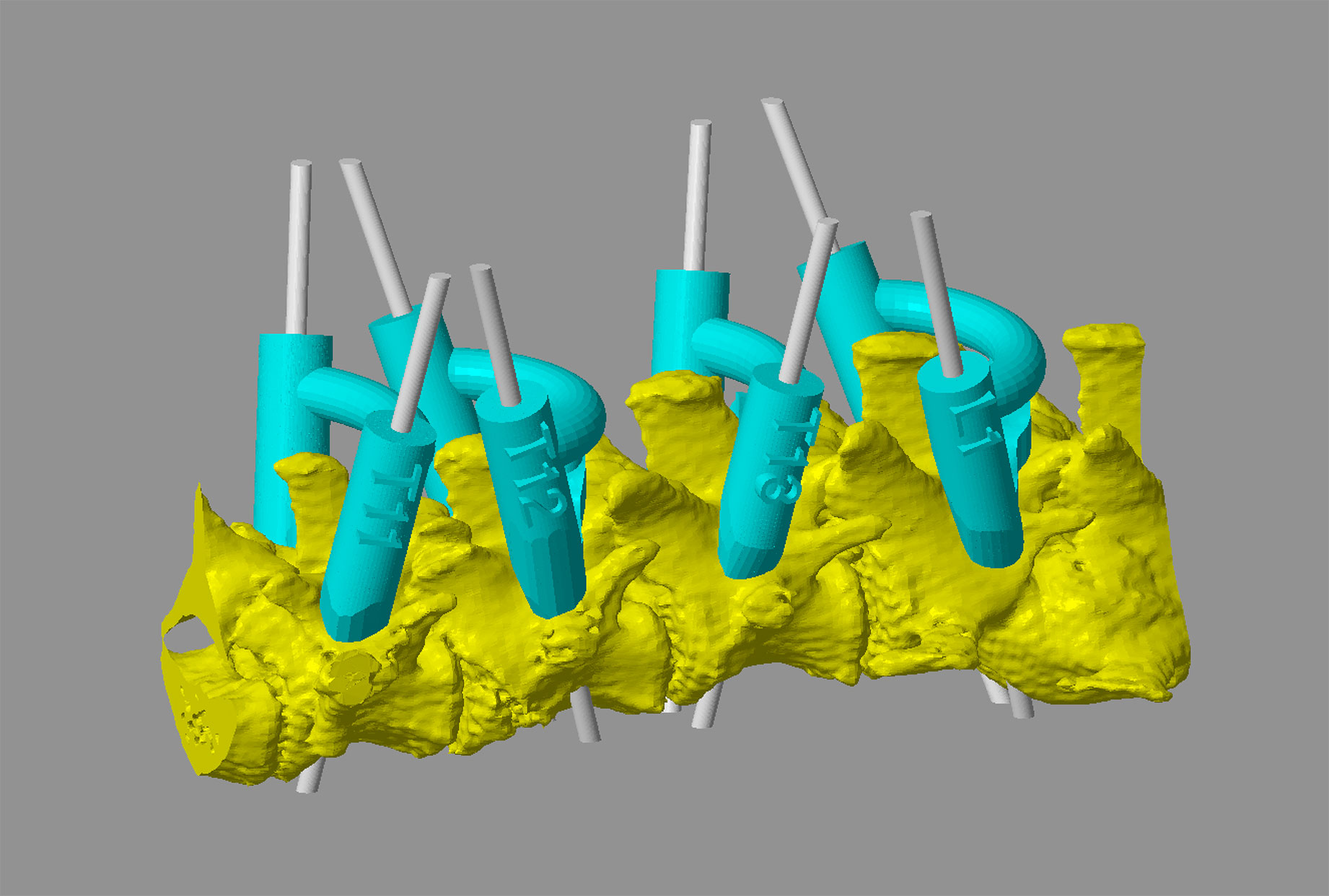
Figure 8 – Intra-operative image from a five year old miniature Dachshund weighing 5kg with a T12 fracture and a T13-L1 acute on chronic extrusion / protrusion. Guides conforming to the laminae of T11, T12, T13 and L1 have been placed for drilling of pedicle screw pilot holes (A and B). CAD image showing virtual guides and trajectories for 1.5mm pilot holes (for 2mm locking screws).
Figure 9 – Pilot hole drilling (video - below). The orientation of the outer aspect of the drill sleeve, and its translucent nature, allow fairly accurate alignment of the drill bit to the central pilot hole. Once in position the trajectory of the drill bit is precisely controlled as long as guide position on the vertebra is maintained.
Figure 10 – A 3D-printed model of the vertebrae with the screw pilot holes included can be used for screw length measurement.
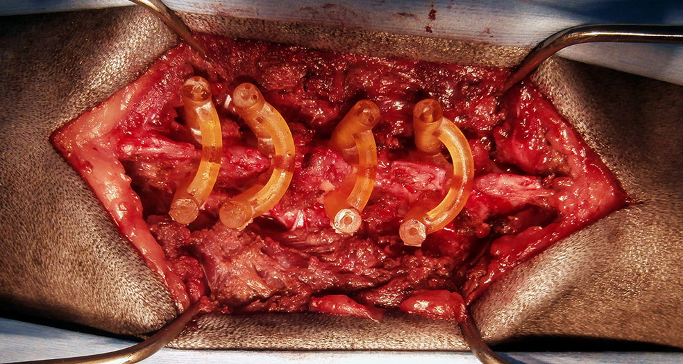
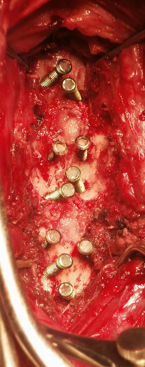
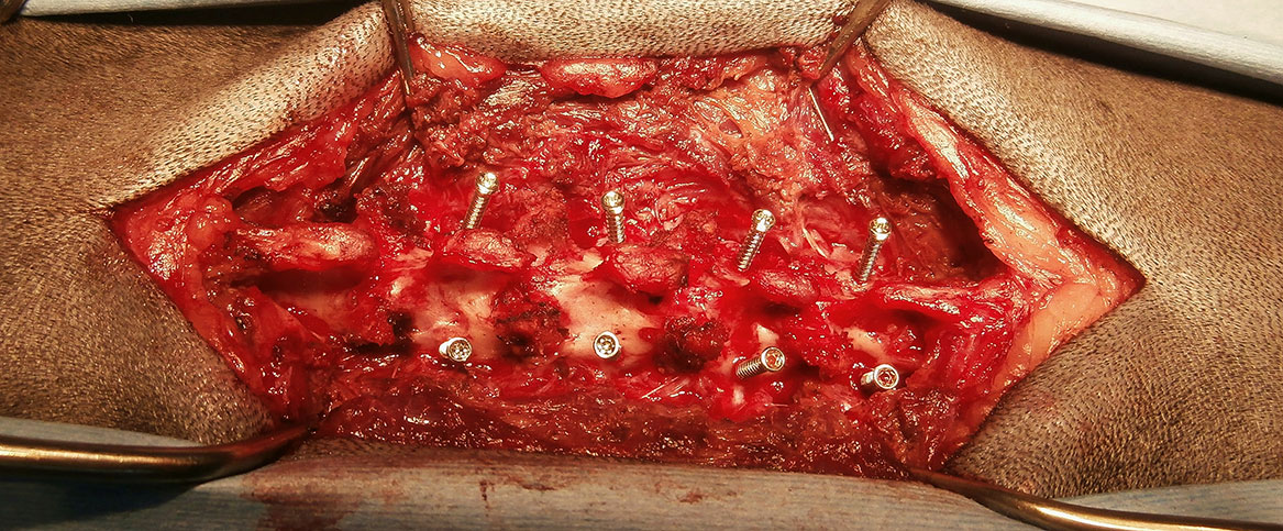
Figure 12 – Intra-operative images showing screw placement. Case 1 - ten titanium locking pedicle screws placed in C5 (four), C6 (four) and C7 (two) (A). Case 2 - eight 2mm locking screws have been placed (B).
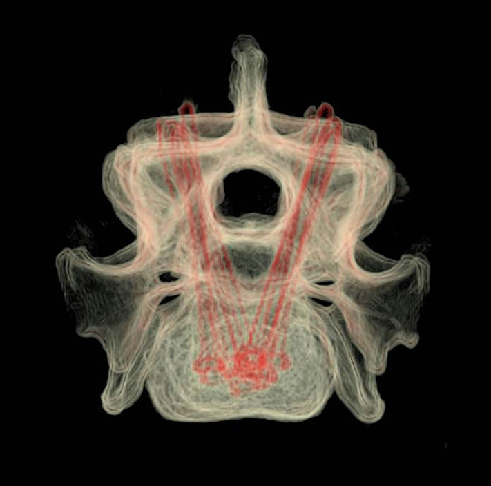
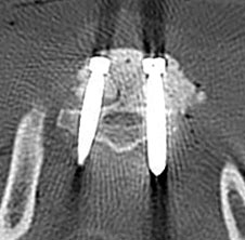
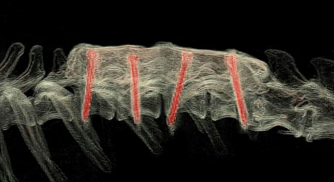
Figure 13 – Case 1 - volume rendered CT images showing screw positioning. Lateral (A), dorsal (B), transverse including all three vertebrae (C) and transverse C6 only (D). Transverse CT images showing screw positioning (image - E, video - F - below).
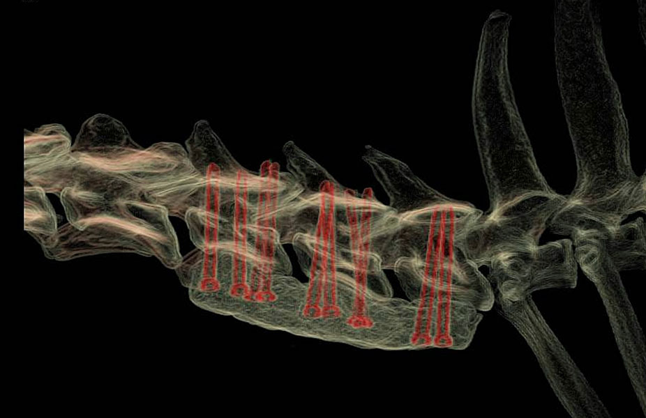
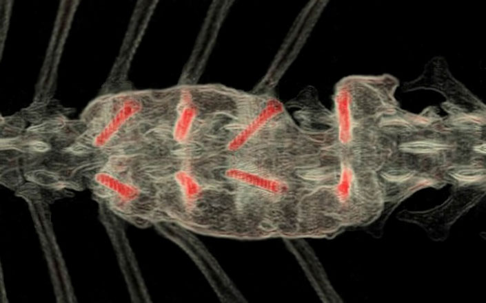
Figure 14 – Case 2 - volume rendered CT images showing screw positioning (A-C). Screw orientations in the frontal plane vary both to avoid the caudal T12 vertebral body fracture, and to avoid the hemilaminectomy site at T13-L1. The discontinuity in the right-sided PMMA column avoids the laminar deficit.
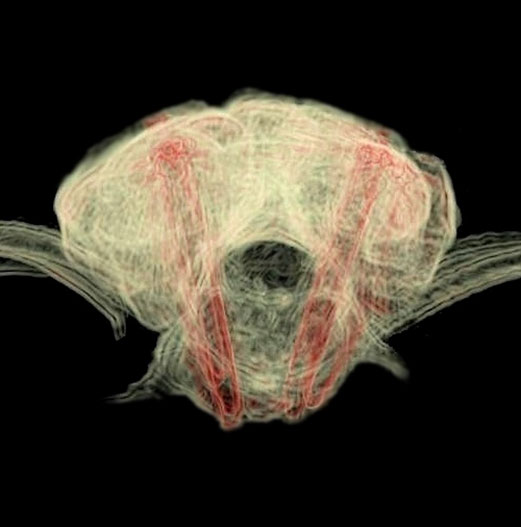
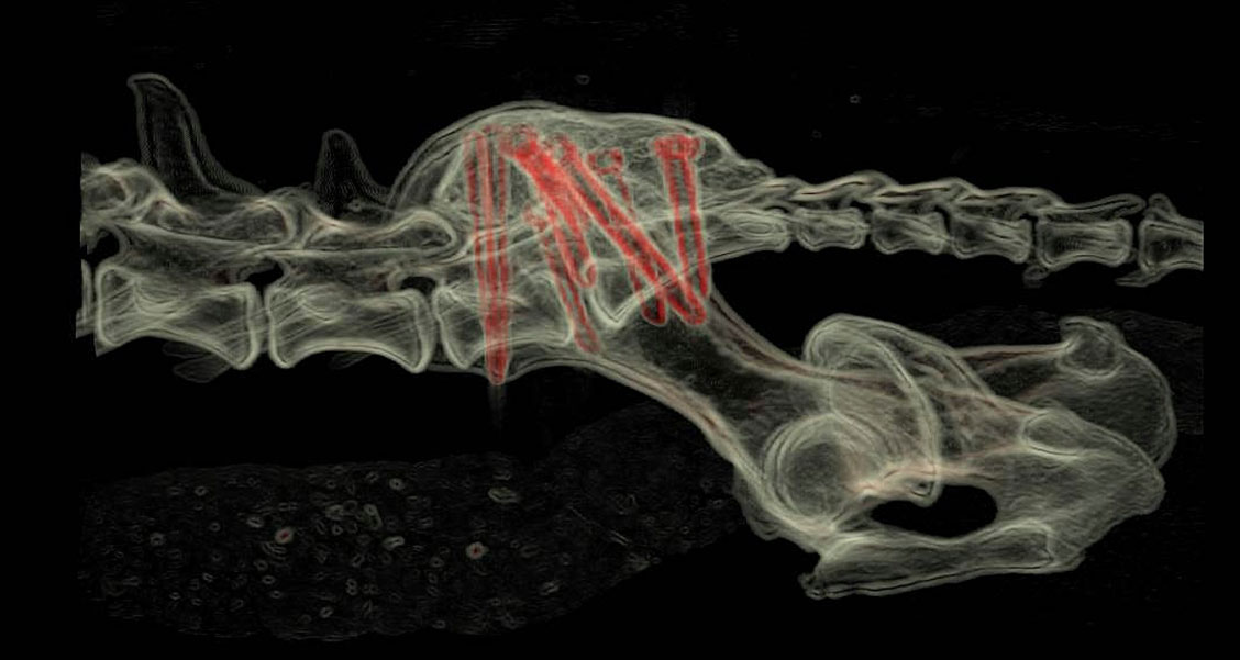
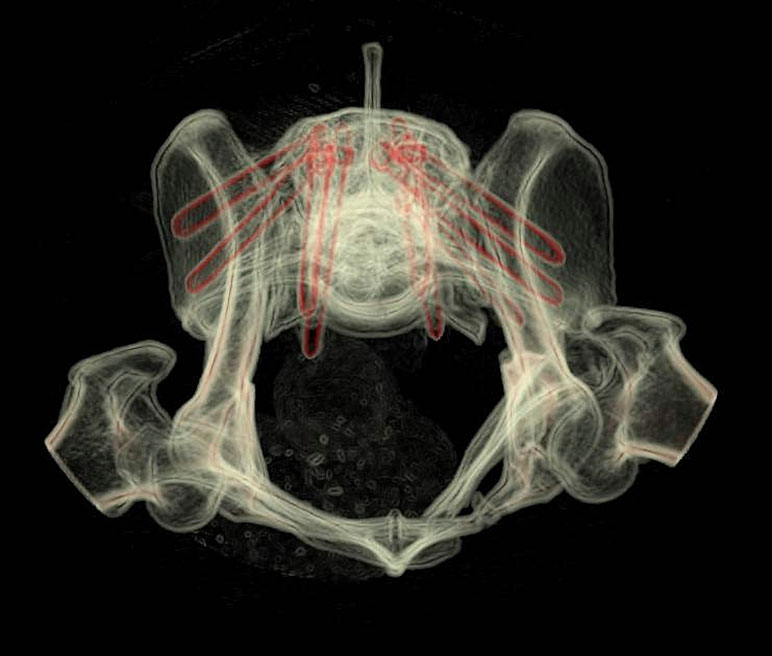
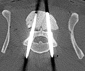
Figure 15 – Volume rendered CT images showing screw positioning following guided placement for treatment of a sacral fracture in a 15 month old cocker spaniel weighing 11kg (A - C). Transverse images of pedicle screw positioning in L7 (D) and the sacrum (E). The L7 screws are 2.7mm locking and the sacral screws 3.5mm locking.
Kyphosis amelioration
Patient-specific drill guides have been used to stabilise multiple vertebrae as part of treatment for kyphotic deformity via a dorsal approach in pugs and French bulldogs. Due to the small size of these patients 1.5mm pedicle screws are placed; following amelioration of the deformity the heads of the screws are bonded with PMMA resulting in stabilisation with reduction in kyphosis angle.
3D Printing
For most cases the following models and guides are printed (Figure 16) –
- Vertebrae to be stabilised – to practice drill guide fit (usually in autoclavable resin)
- Drill guides (autoclavable and biocompatible resin)
Please see Price Guide for additional information
Figure 16 – A 3D-printed vertebra (autoclavable) and the corresponding drill guide (biocompatible and autoclavable). In most case two or more vertebrae and guides would be supplied.
©Copyright 2017 - Vet 3D | Terms & Conditions | Cookie Policy