- Login
- Sign Up
- Online referral form
This site is optimised for modern web browsers, and does not fully support your version of Internet Explorer, some sections of the website may not work correctly such as web forms


Other Deformities
This represents a diverse group of limb deformities ranging from the relatively straightforward (for example a single bone fracture malunion with a normal contralateral limb) to the very complex (such as atypical developmental deformities with compensatory changes affecting other bones and associated joint pathology).
Single bone deformities
Such cases are typically more straightforward to assess and plan than for example developmental antebrachial deformities since CAD modelling permits the mirrored, contralateral bone to be used as a template for realignment.
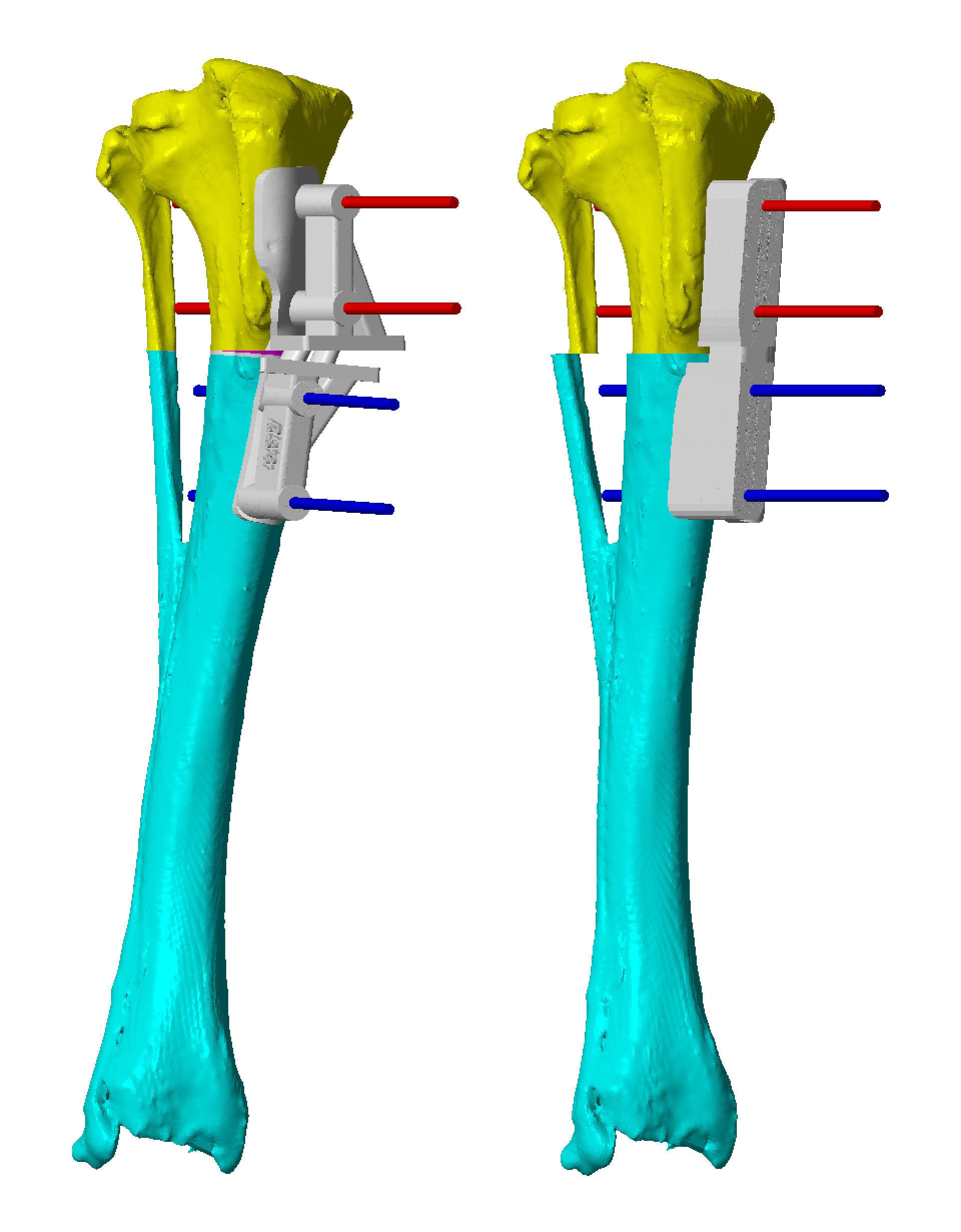
In this way, following virtual osteotomy of the deformed bone, the orientation and position of the epiphyses can be aligned to those of the contralateral limb (Figure 1). The proximal and distal segments are then reduced; in most cases some shortening is unavoidable (especially with a closing wedge osteotomy), albeit that the relative angular orientations of the joint surfaces are maintained (Figure 2). Guide systems can be designed to facilitate closing, neutral and opening wedge osteotomies at their respective CORAs, although acute opening wedges can prove challenging due to soft tissue tension. In the femoral deformity shown in Figure 3, an opening wedge was planned to maximise femoral length, however intra-operatively this degree of acute lengthening was prevented by soft tissue tension. A secondary osteotomy guide had been prepared such than conversion to a neutral wedge was possible (Figure 4). This case required an additional tibial osteotomy to correct compensatory deformity (Figure 5).
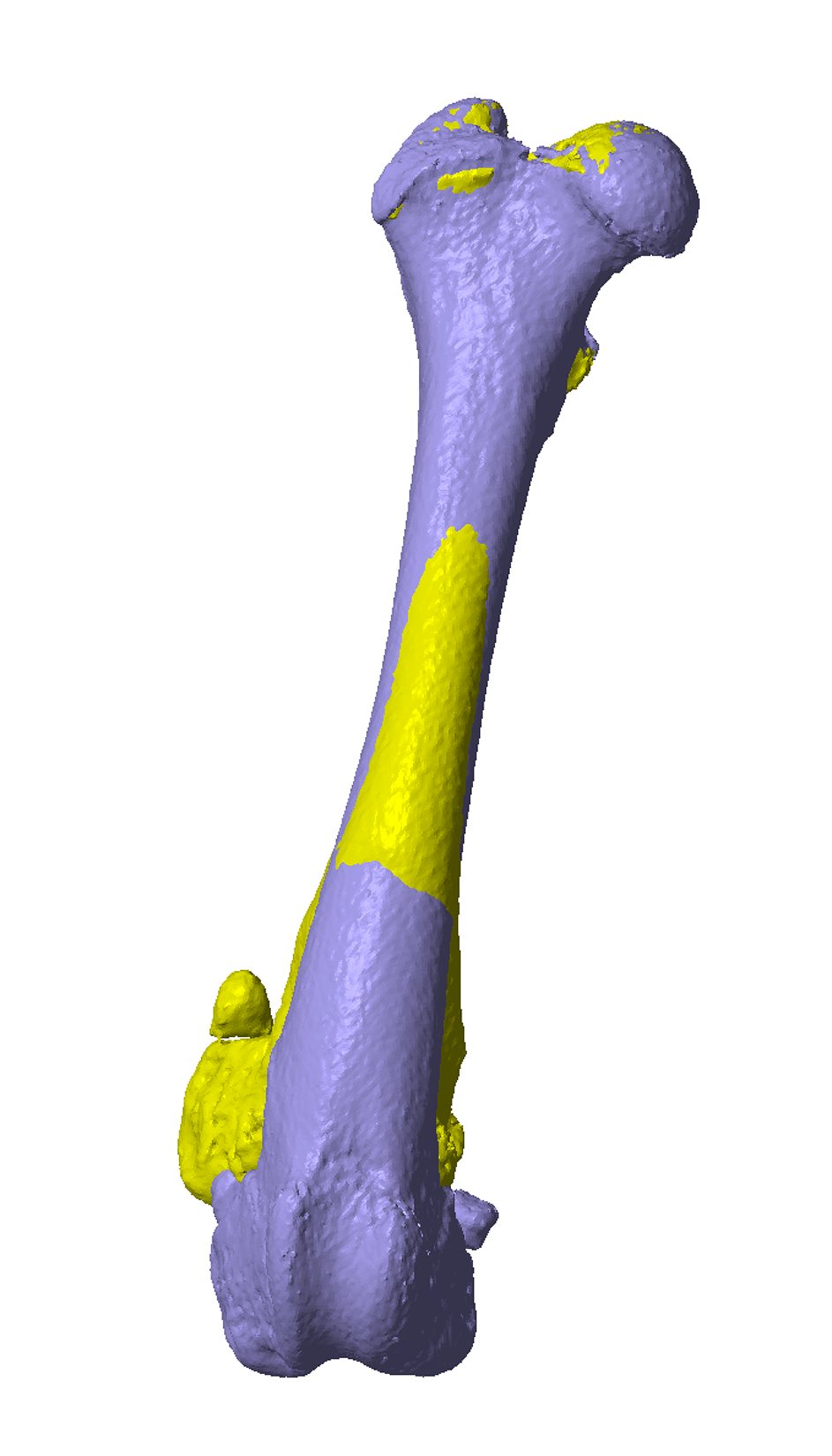
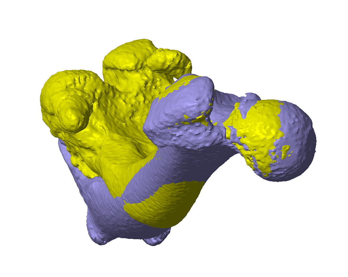
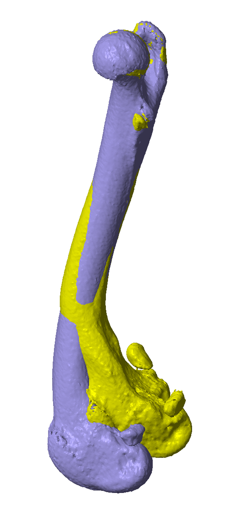
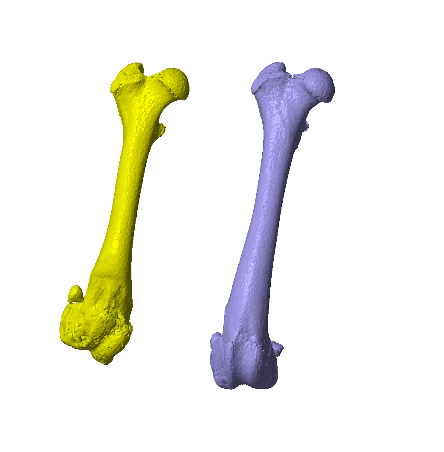
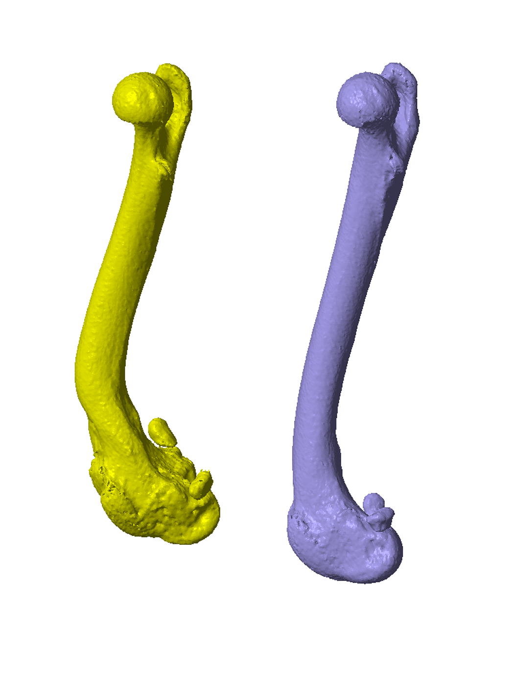
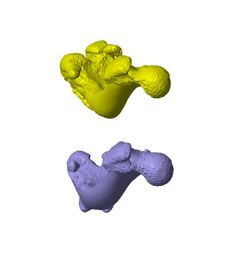
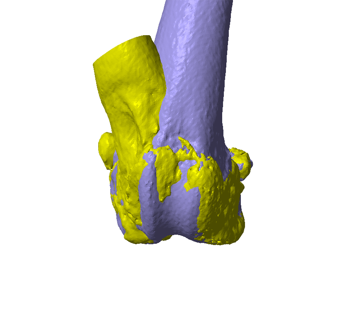
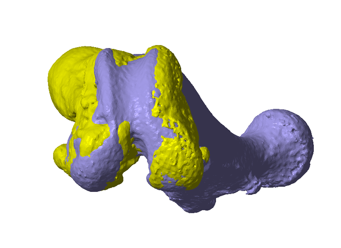
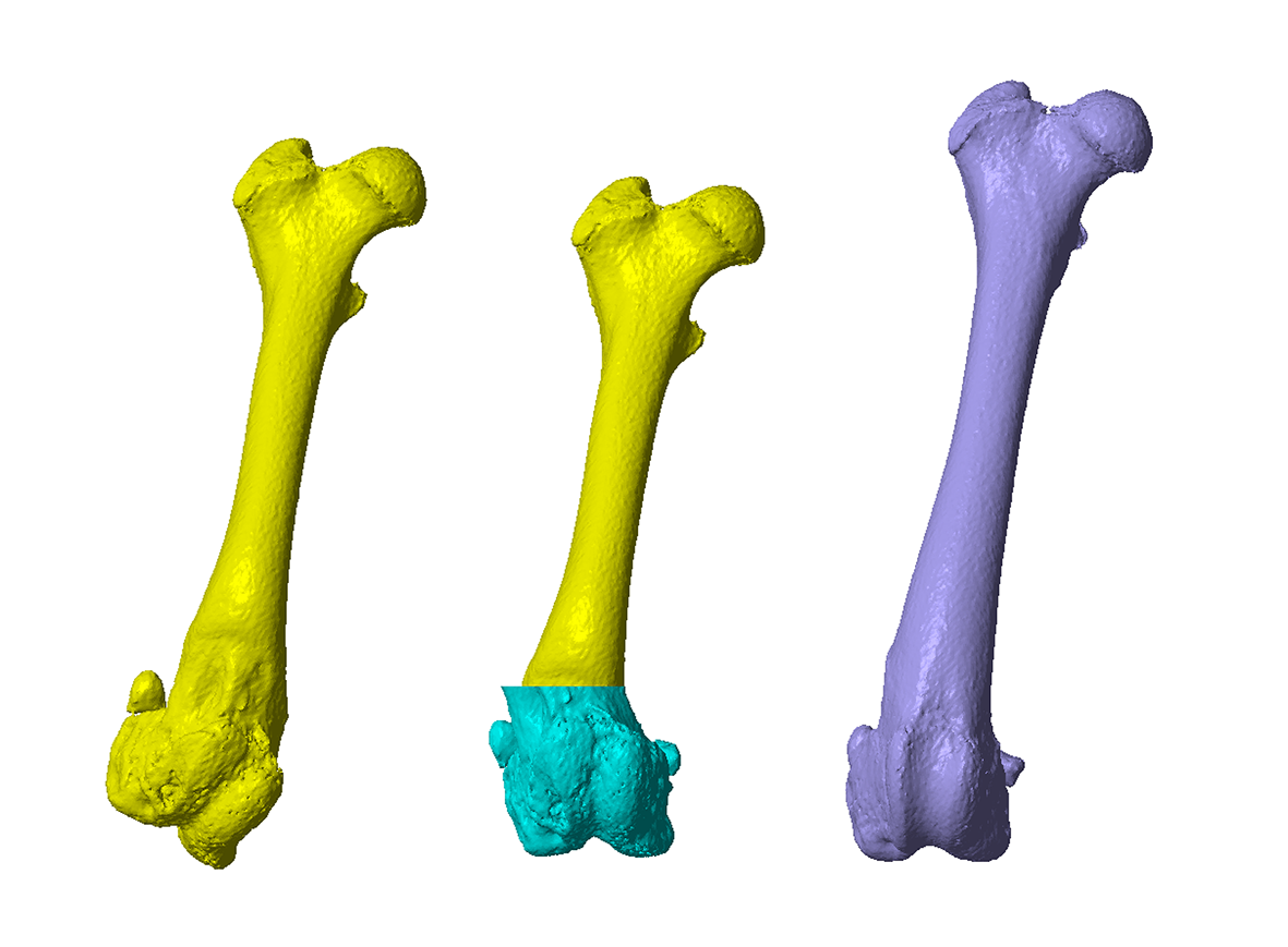
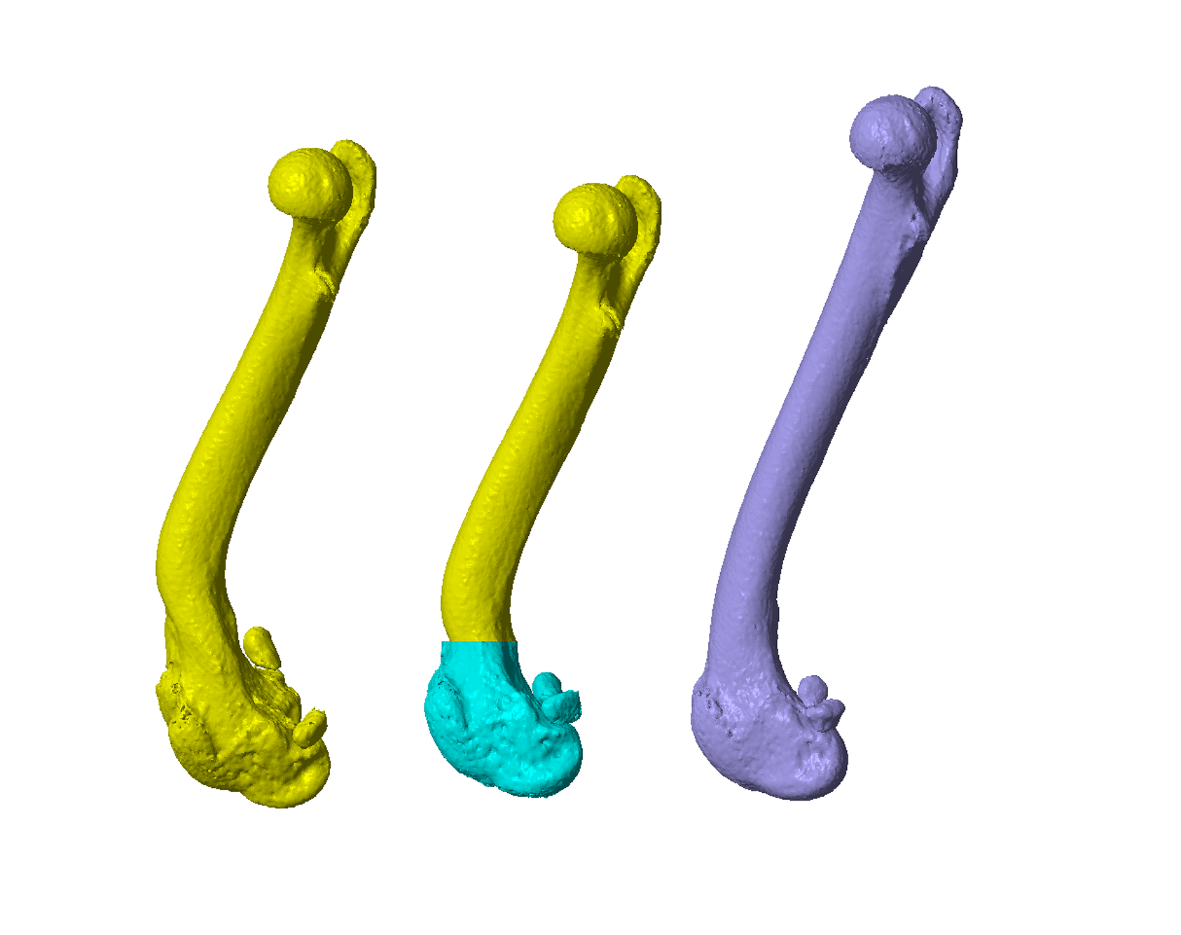
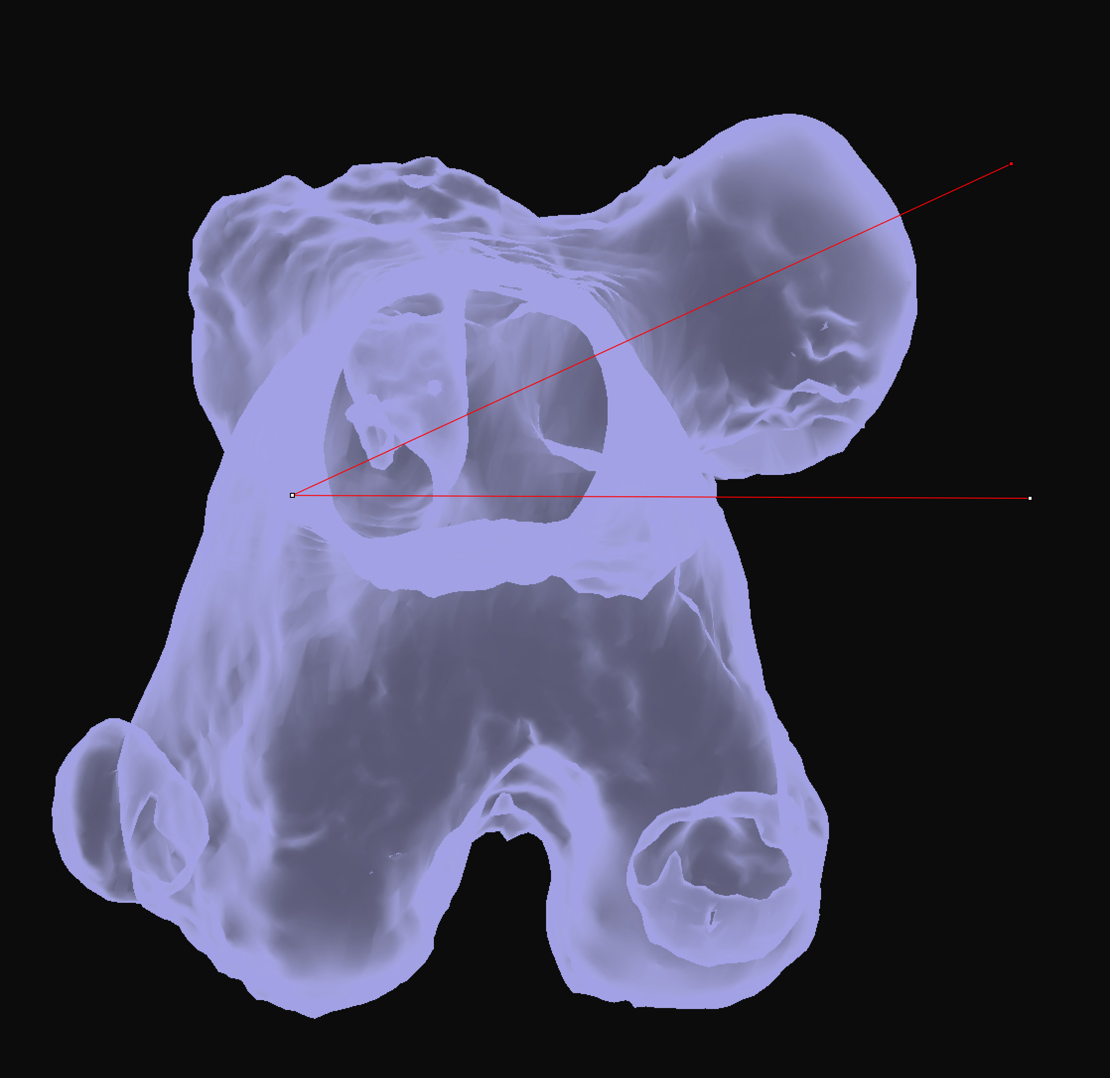
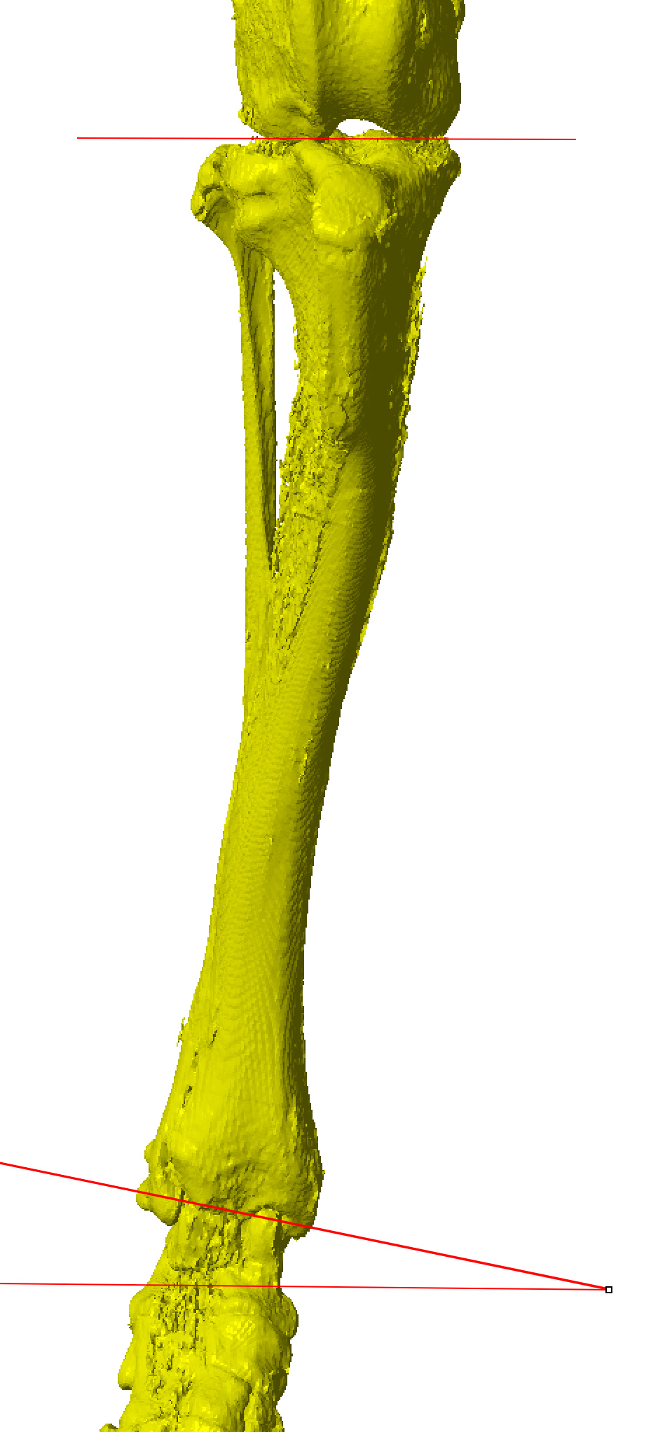
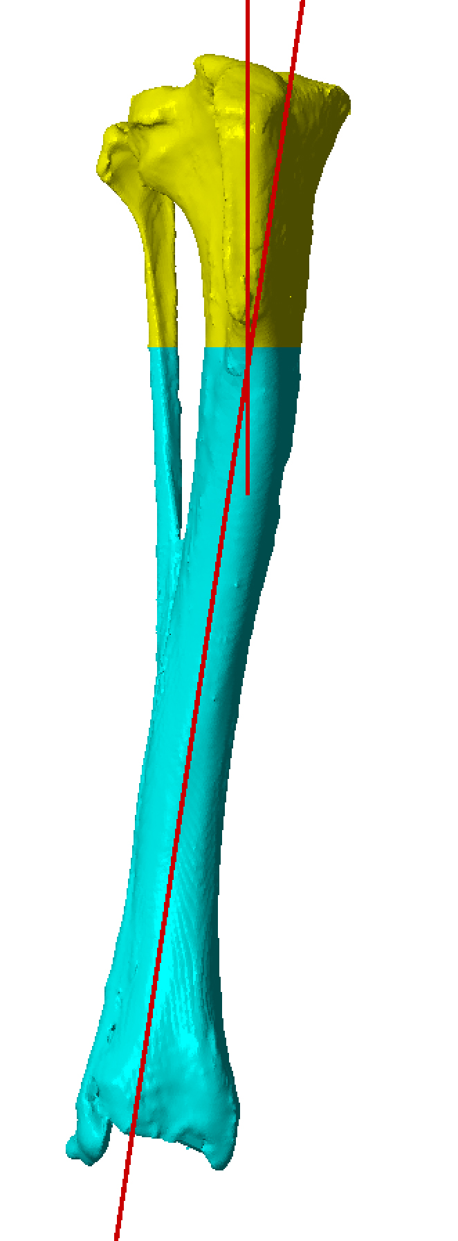
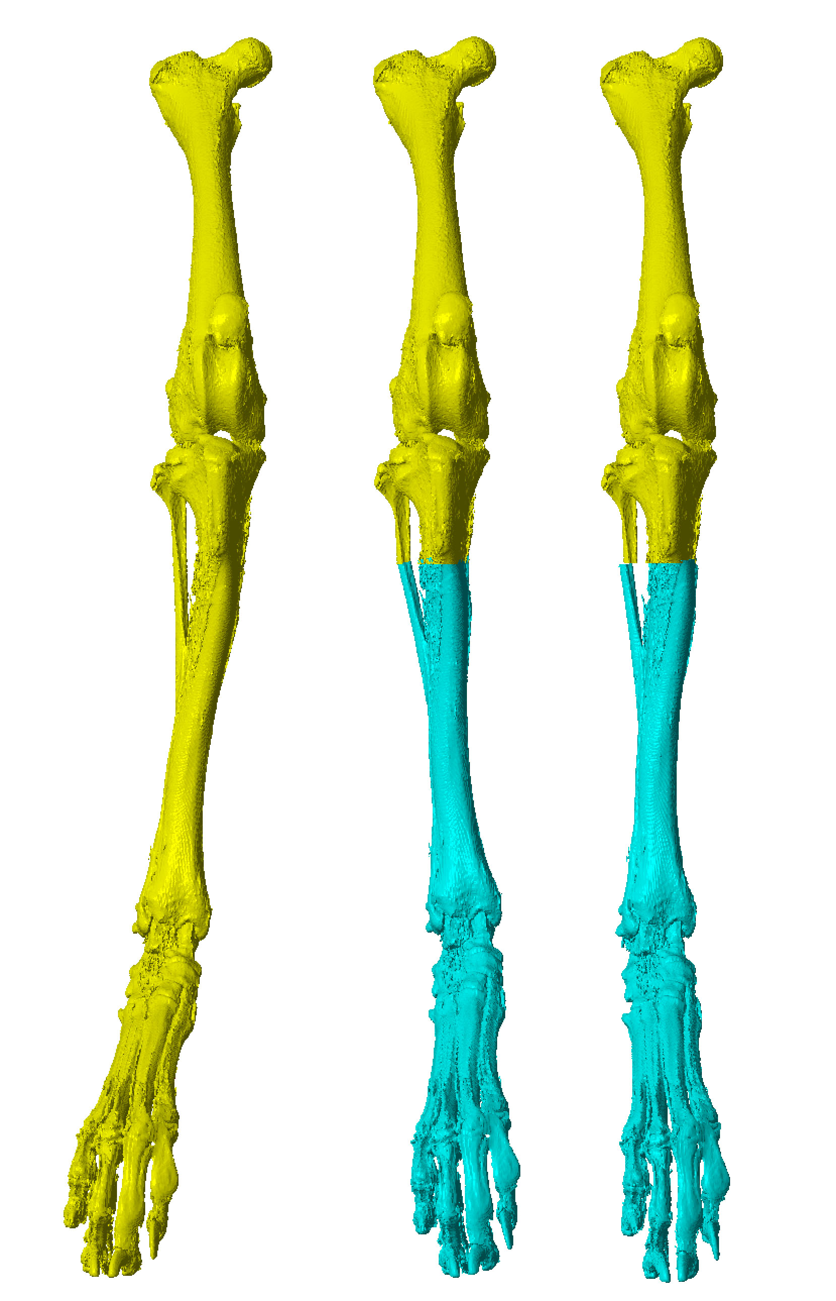
Figure 1 – The position and orientation of the proximal epiphyses of the normal, mirrored bone (purple) and the affected bone (yellow) are matched (superimposed images A-C; side-by-side D-F). Note the moderate valgus, procurvatum and torsional deformities. A virtual osteotomy is performed, and the distal epiphyses similarly matched (G-I).
Figure 2 – The proximal and distal segments have been reduced following a virtual closing wedge ostectomy (A-C). The osteotomy was performed at the frontal plane deformity CORA and was therefore distal to the sagittal plane CORA resulting in translation following reduction in that plane (thus the cranial cortical step). The converse situation resulted in unacceptable medial translation of the distal segment after reduction. Note that despite some shortening, the angular orientations (and x and y plane positions) of the proximal and distal epiphyses are maintained after reduction (D).
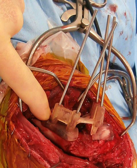
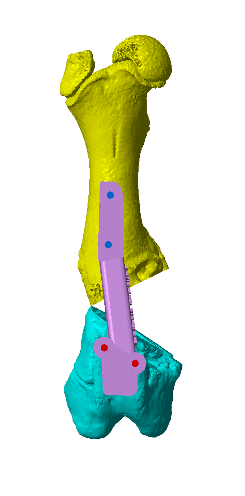
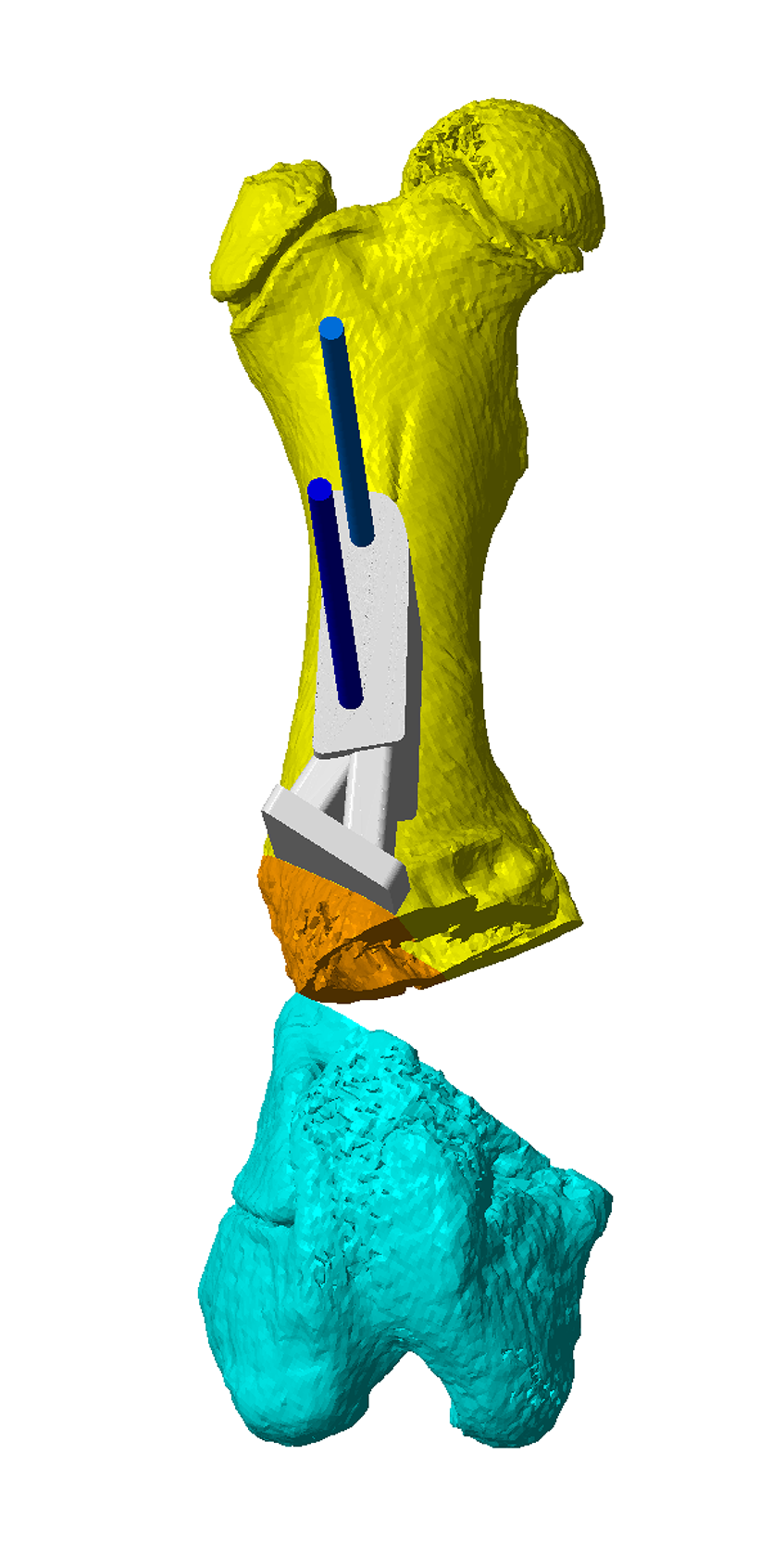
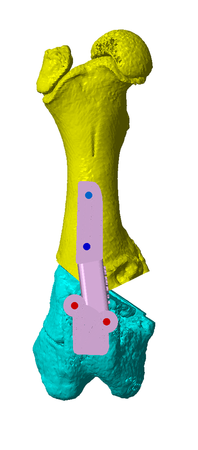
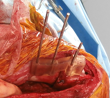
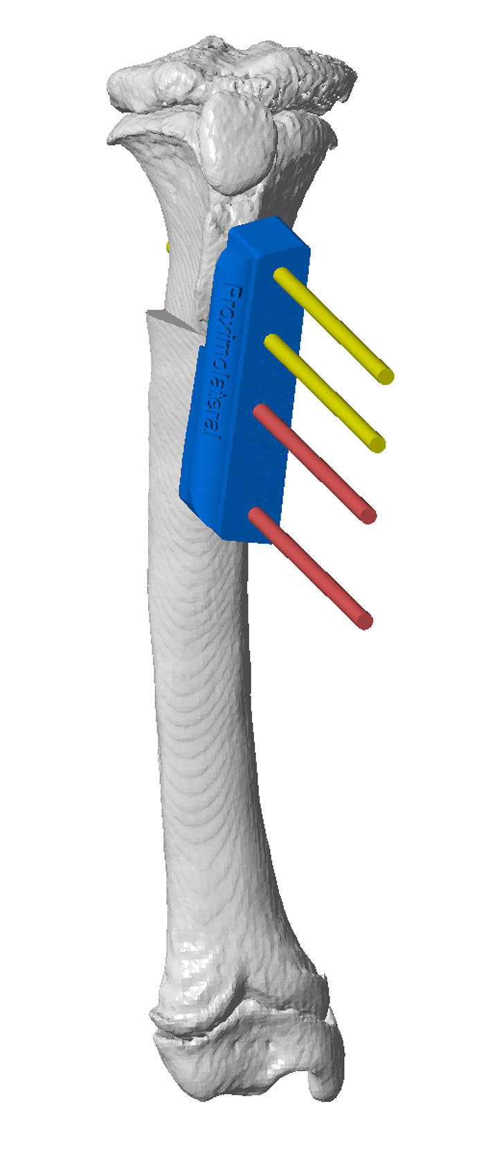
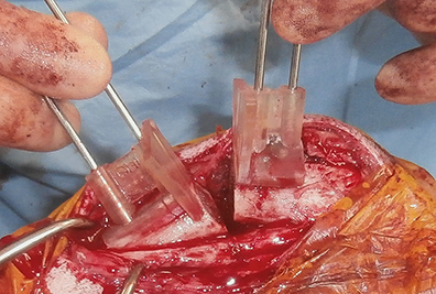
Figure 3 – A severe femoral deformity secondary to partial closure of the medial aspect of distal femoral physis (A). The position and orientation of the proximal epiphyses of the mirrored contralateral and affected femur have been matched. A virtual osteotomy at the CORA has been made, and the distal epiphyses matched (B). The osteotomy guide is designed to orientate the saw blade for planned osteotomy (C). Intra-operative image showing the osteotomy guide in-situ and secured with four 2.4mm Ellis pins (D). The osteotomy has been completed parallel to the guide plane (E). Alignment of the Ellis pins by the reduction guide results in an opening wedge osteotomy with the planned relative orientations of the proximal and distal segments (F).
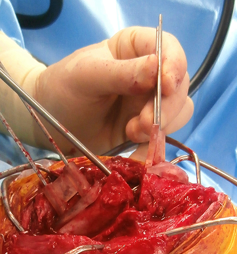
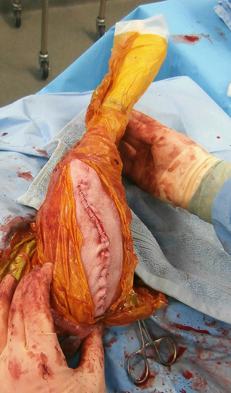
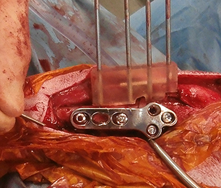
Figure 4 – A secondary osteotomy guide fits over the proximal Ellis pins and orients the saw blade for a further femoral osteotomy (A). The saw blade is aligned parallel to, and in contact with, the osteotomy plane of the guide (B). A secondary reduction guide then reduced the proximal and distal segments with the same orientation, but in a neutral wedge configuration (C). Intra-operative image showing osteotomy segment reduction (D). Note that the distal Ellis pins have been shortened; this can facilitate placement of the reduction guide. Conversion from an opening to neutral wedge resulted in shortening of approximately 12mm which was sufficient to allow reduction without excessive soft tissue tension. A 3.5mm LCP has been placed adjacent to the reduction guide (E).
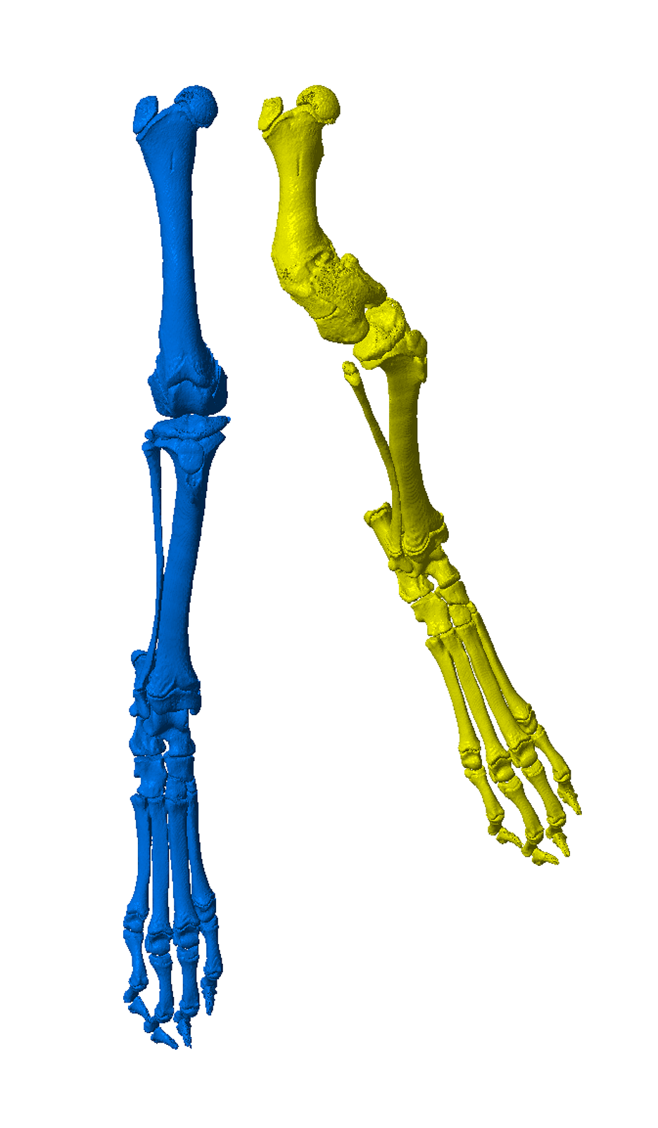
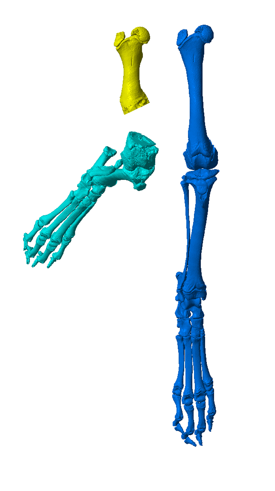
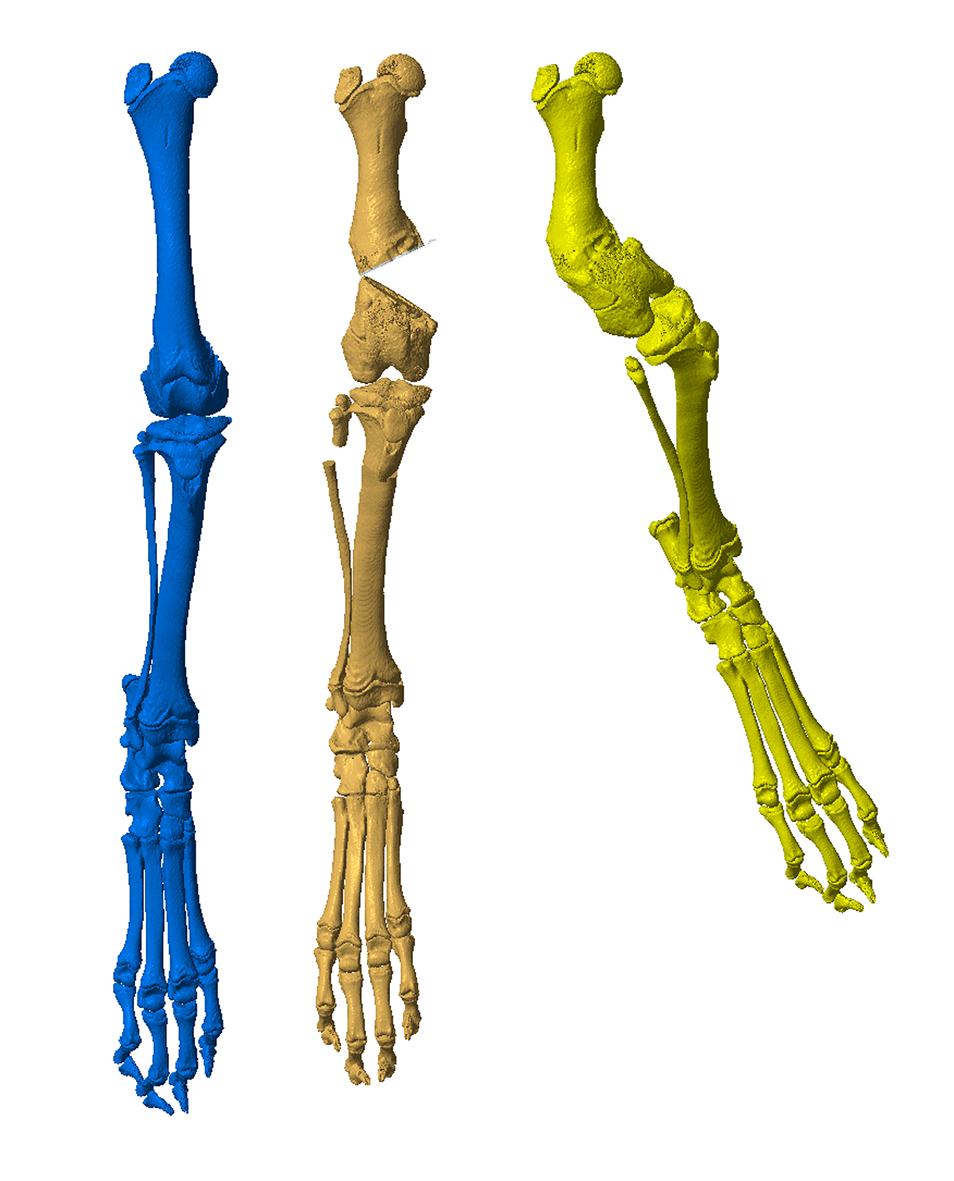
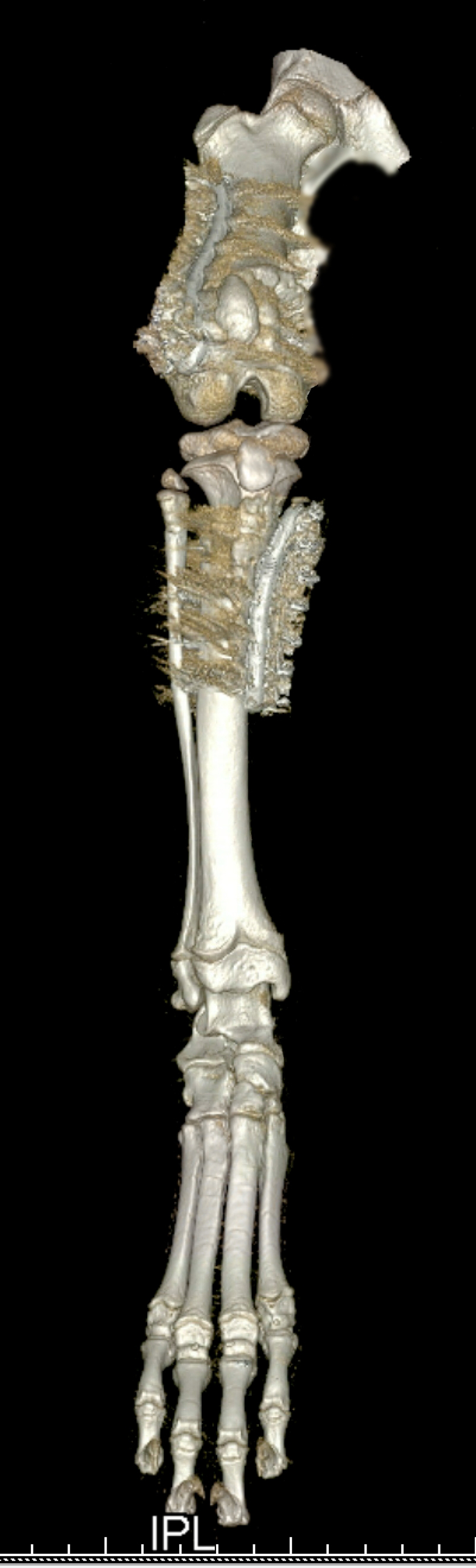
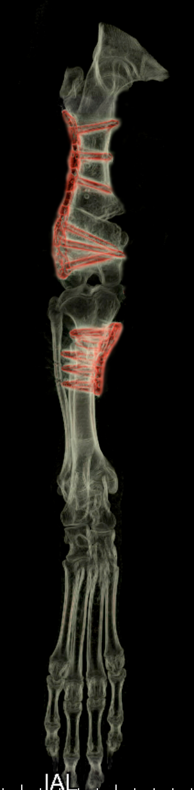
Figure 5 – Position and orientation matching of the mirrored contralateral and affected proximal tibial epiphyses revealed significant compensatory tibial valgus (A). Corresponding limb alignment following completion of the femoral osteotomy (B). Osteotomy and reduction guides were designed to facilitate a closing wedge ostectomy (C and D). The tibial osteotomy guide in-situ (E). The osteotomies have been completed parallel to the guide planes (F) and the segments reduced using the reduction guide (G). A locking TPLO plate is applied adjacent to the guide, (H). Final CAD alignment (gold) with mirrored contralateral (blue) and original conformation (yellow) (I). CT images pre-op (J) and post-op (K and L).
Complex deformities
These include developmental deformities associated with abnormal physeal growth or other forms of anomalous bone development, and are often associated with compensatory deformities of other bones and in some cases pathological changes to associated joints.
As discussed above, if the contralateral limb is normal, mirrored vitual models of the normal bones can be used as a templates for realigned of the affected bones. Unfortunately in many cases there is bilateral involvement, necessitating more traditional CORA-based conformational quantification and / or CAD based iterative limb realignment following virtual osteotomies and limb segment reorientation.
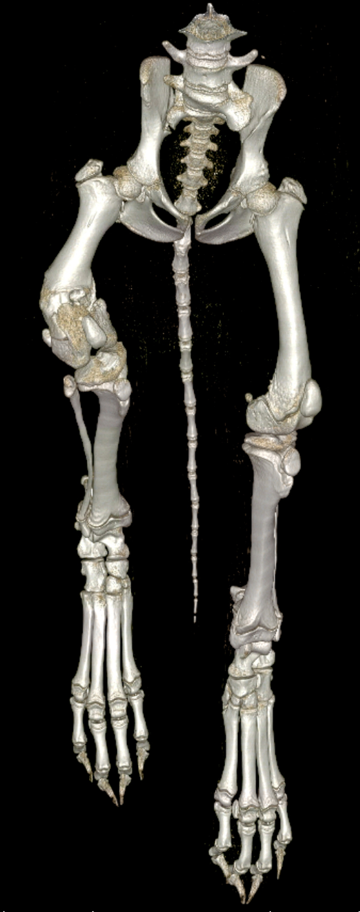
The images in Figure 6 represent key stages in the CAD-based analysis of a complex right pelvic limb deformity in a nine month old German shepherd dog. The contralateral limb was affected to a lesser degree precluding its use as a template for optimal realignment. Analysis of femoral conformation revealed relatively normal anteversion, but an abnormal varus angle of -2 degrees (aLDFA 88 degrees). Additionally tibial conformation was abnormal with 11 degrees valgus. These deformities were non-compensatory, however the tibial deformity was considered more likely to be clinically significant. A virtual 11 degree medially-based closing wedge ostectomy was performed at the frontal plane CORA resulting in good frontal plane limb alignment but with obvious external rotation of the tarsus and paw. Even using volumetric data torsion can be difficult to accurately quantify using traditional techniques, however the ability to reorientate the distal osteotomy segment in the CAD allowed iterative internal rotation until appropriate alignment of the tarsus and paw was achieved. Osteotomy and reduction guides were designed to facilitate the planned valgus and torsional correction; the position of the Ellis pins and reduction guide was designed to permit medial plating.
The combination of CORA-based standardised methodology for quantification of angular deformities with the freedom to iteratively adjust osteotomy segment orientation in six degrees of freedom enables the surgeon to both accurately plan an optimal correction and to visualise, and if necessary adjust, the resultant conformation. The subsequent use of patient-specific surgical guides facilitates translation of this plan to the patient in theatre.
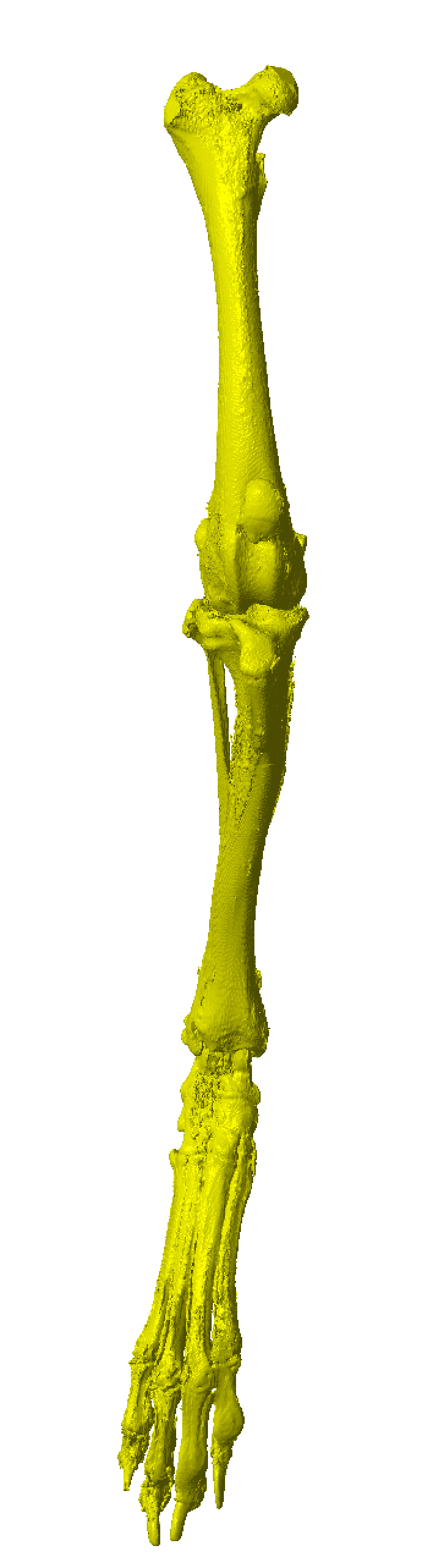
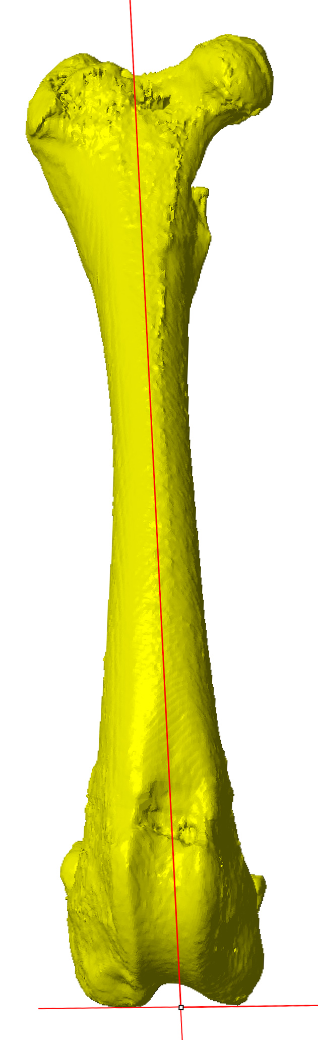
Figure 6 – CAD image showing overall alignment of the right pelvic limb of a nine month old German shepherd dog (A). The femur was isolated and orientated to permit measurement of femoral varus angle -2 degrees (aLDFA 88 degrees) (B) and anteversion (approximately 20 degrees) (C). The bone model was reoriented to allow quantification of tibial conformation (11 degrees valgus) (D) with a CORA at the level of the distal tibial crest (E). A virtual 11 degree medially-based closing wedge ostectomy was performed at the CORA resulting in improved frontal plane limb alignment but with obvious external rotation of the tarsus and paw (F, central image). Internal rotation of the distal osteotomy segment by 14 degrees resulted in much improved tarsal and paw alignment (F, right image). Osteotomy and reduction guides were designed to facilitate the planned ostectomy and torsional correction; the position of the Ellis pins and reduction guide was designed to permit medial plating (G).
Deformity assessment, surgical planning and 3D-printing
Deformity assessment and surgical planning
This can be relatively straightforward in simple cases (for example single bone malunions with a normal contralateral limb) but may be significantly more difficult in complex cases. DICOMs can be uploaded for assessment as required, options include –
- Preliminary assessment –
- CAD-based overview of bone and overall limb alignment
- E-mail review of options for more detailed assessment, surgical planning, and cost estimates
- Generally no charge
- CAD-based deformity assessment -
- Detailed CAD-based assessment of bone conformation and limb alignment
- E-mail or screen-share review
- Option for proceed to guide system design
- Generally a charge is made for this service dependent on time required – see Pricing Guide for details
- Surgeon-specified surgical planning
- E-mail or screen-share review following surgeon-specified deformity corrections
- Guides can be created based on surgeon specifications
- Generally no charge
- Other assessment
- Tell us how we can help!
Guide design and 3D-printing
Osteotomy and reduction guides are designed, with the standard print option including –
- Pre-op bone or limb segment – to practice osteotomy guide fit (usually in autoclavable resin)
- Post-op bone or limb segment, with reduction guide footprint in-situ – for plate precontouring (white, non-autoclavable resin)
- Osteotomy and reduction guides (autoclavable and biocompatible resin)
Other print options can be surgeon specified.
©Copyright 2017 - Vet 3D | Terms & Conditions | Cookie Policy